ClioSport.net

Register a free account today to become a member!
Once signed in, you'll be able to participate on this site by adding your own topics and posts, as well as connect with other members through your own private inbox!

  • When you purchase through links on our site, we may earn an affiliate commission. Read more here.

Electronics


sn00p

ClioSport Club Member
  A blue one.
Anybody else into electronics? I've been involved in electronics for 20+ years commercially, designing embedded systems.

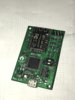
Got bored at home the other week so decided to see how far open source design software had come, so knocked up a small design (wifi and i2c breakout) and had the PCB's made in china for next to nothing.

Absolutely nuts how cheap it is to get PCB's made in china, cost me £6.50 for 10 including shipping!
 

Attachments

  • IMG_2831.JPG
    IMG_2831.JPG
    430.5 KB · Views: 124

Ol’ Tarby

ClioSport Moderator
  Clio 220 Trophy
So what's it's do?

I've got an A level in electronics, and did two years electronic engineering at university. Don't really use it massively these days so have forgotten a lot of stuff, but I still know the basics and deal with equipment using I²C and raspberry pi's etc every day
 
  Flamer Barn Find
I'm an electronic and electrical engineer. I'm on the service and maintenance side of things in the medical industry which is a nice mix of mechanical and electrical but i'm one of the only guys at work who can fault find to a component level.

I'd recommend JLCPCB who do 10 x 100x100mm PCB's for £2.00. I built a little diagnostic interface box a few months ago for all the other engineers and managed to get 2 on a 100x100mm board. Cost me 2 quid for 20 diagnostic interfaces plus components.
 

sn00p

ClioSport Club Member
  A blue one.
So what's it's do?

I've got an A level in electronics, and did two years electronic engineering at university. Don't really use it massively these days so have forgotten a lot of stuff, but I still know the basics and deal with equipment using I²C and raspberry pi's etc every day

Not a lot. It was mainly a test of the design software (KiKad) and the board manufacturer, I wanted an excuse to use the teeny tiny ARM SWD connector, it's common to find dev boards with the standard size SWD connector, but not the tiny one. I just wanted to have a play with the ESP-12F module as well, I have everything up and running, freertos & the networking. I can use it to test/use various i2c devices, but I'm now going to do a full design knowing that the stuff works.

I'm an electronic and electrical engineer. I'm on the service and maintenance side of things in the medical industry which is a nice mix of mechanical and electrical but i'm one of the only guys at work who can fault find to a component level.

I'd recommend JLCPCB who do 10 x 100x100mm PCB's for £2.00. I built a little diagnostic interface box a few months ago for all the other engineers and managed to get 2 on a 100x100mm board. Cost me 2 quid for 20 diagnostic interfaces plus components.

I'm originally a software engineer, but spending 20 years working with schematics and debugging hardware means I have a very good grasp of electronics now, it's especially useful when I'm given a schematic to start with and I check whether I can see any obvious errors or whether a signal needs to go to a specific pin on the micro etc.

Yep, I had these made by JLCPCB, I could have used the panellise option and had 20 instead of 10, but I only really wanted to one just so that I could do and end to end test of the tools and devices I had chosen.

I've also designed medical equipment in the past, stuff for testing for cystic fibrosis, got certification in the states!
 
  Flamer Barn Find
I'm originally a software engineer, but spending 20 years working with schematics and debugging hardware means I have a very good grasp of electronics now, it's especially useful when I'm given a schematic to start with and I check whether I can see any obvious errors or whether a signal needs to go to a specific pin on the micro etc.

Yep, I had these made by JLCPCB, I could have used the panellise option and had 20 instead of 10, but I only really wanted to one just so that I could do and end to end test of the tools and devices I had chosen.

I've also designed medical equipment in the past, stuff for testing for cystic fibrosis, got certification in the states!

I left school at 16 and managed to find a good company to put me through all training. Just before I left them I decided I wanted off the tools and was sick of travelling and spent 6 months working in the design department as a trainee. f**king hated being stuck in the office and being off the tools.

Fault finding to a component level has helped me out a hell of a lot throughout my career.

JLCPCB are excellent tbh.

Getting stuff approved in the states is pretty impressive as the FDA don't f**k about. I worked in the IVD industry fixing large automated blood testing kit and we got audited by the FDA every year. Then moved into X-Ray which is so heavily regulated it's incredible.
 

Andy_con

ClioSport Club Member
  clio 182
I love electronics, the things you can do these days are amazing. the things people do are amazing.

sadly I know f**k all about electronics and coding :(

when I was at school electronics and coding wasn't a thing, it was do you want to be a fireman, policeman or doctor when you leave school.

if I knew electronics and coding the things id do!! id be rich!
 

Andy_con

ClioSport Club Member
  clio 182
this forum is full of very interesting and intelligent people, if anyone needs a good electronics project just drop me a PM ;)
 
  Flamer Barn Find
I love electronics, the things you can do these days are amazing. the things people do are amazing.

sadly I know f**k all about electronics and coding :(

when I was at school electronics and coding wasn't a thing, it was do you want to be a fireman, policeman or doctor when you leave school.

if I knew electronics and coding the things id do!! id be rich!

What is this project you speak of ;) The problem with doing things like this as a day job - you can't be arsed to do them when you get home. I've had so many side ventures related to my day job (fixing macbooks, SMD Conversions on cars, fixing Pioneer CDJ's and so on) and end up knobbing them because it's too close to my day job.

When I was at school Electronics had only just came about as a subject - most of it based on 555's and 4017's. In my last year of school we did move onto PIC16F microcontrollers which were incredibly expensive at the time and we just kept f**king blowing them up. I was predicted good grades at school and parents and the school wanted me to go off and study medicine. I was f**king sick of education and told them i was leaving school at 16 and wanted to be a sparky.
 

sn00p

ClioSport Club Member
  A blue one.
I love electronics, the things you can do these days are amazing. the things people do are amazing.

sadly I know f**k all about electronics and coding :(

Designing circuits is pretty easy (if your brain is wired that way), laying out a PCB can be fairly tricky depending on the number of layers you use and how compact you want to make it.

when I was at school electronics and coding wasn't a thing, it was do you want to be a fireman, policeman or doctor when you leave school.

I'm old enough that neither electronics or computing was taught at school! ?
 

Andy_con

ClioSport Club Member
  clio 182
What is this project you speak of ;) The problem with doing things like this as a day job - you can't be arsed to do them when you get home. I've had so many side ventures related to my day job (fixing macbooks, SMD Conversions on cars, fixing Pioneer CDJ's and so on) and end up knobbing them because it's too close to my day job.

When I was at school Electronics had only just came about as a subject - most of it based on 555's and 4017's. In my last year of school we did move onto PIC16F microcontrollers which were incredibly expensive at the time and we just kept f**king blowing them up. I was predicted good grades at school and parents and the school wanted me to go off and study medicine. I was f**king sick of education and told them i was leaving school at 16 and wanted to be a sparky.

my dragons den idea - PM discussions only sorry ;)

I hear what your saying, I suppose it depends how fun the project is really. ive no idea if you will find it exciting?

I hated school, didn't do home work or study, my best grade was a D. I just wanted to leave and get a job, so that's what I did.
 

Andy_con

ClioSport Club Member
  clio 182
Designing circuits is pretty easy (if your brain is wired that way), laying out a PCB can be fairly tricky depending on the number of layers you use and how compact you want to make it.


I'm old enough that neither electronics or computing was taught at school! ?
my brain isn't wired that way sadly :( ill stick to cnc machines.

what I was getting at was cos it wasn't taught at school I wasn't interested in it. its only of recent years its become of huge interest, I just wish I had time among all my other hobbies to add electronics
 

sn00p

ClioSport Club Member
  A blue one.
In my last year of school we did move onto PIC16F microcontrollers which were incredibly expensive at the time and we just kept f**king blowing them up

I started messing about with PIC16C84 (the original version before they changed the flash technology and it became the 16F84), built my own programming circuit for it connected to the parallel port of my PC.
 

R3k1355

Absolute wetter.
ClioSport Club Member
Wow thats mega cheap, I have a circuit board design I wanted making up but don't know how to go about it.
Also I have no idea what the design actually means, I literally have a picture from the internet.

6468d1208501330-dwell-reducer-circuit-toyota-cops-dwell-schem.gif


6469d1208502122-dwell-reducer-circuit-toyota-cops-dwell-pcb.gif
 

sn00p

ClioSport Club Member
  A blue one.
Wow thats mega cheap, I have a circuit board design I wanted making up but don't know how to go about it.
Also I have no idea what the design actually means, I literally have a picture from the internet.

top image is the circuit diagram which gives you the types and values of the various components.

The bottom image is a composite picture of the top and bottom PCB layers. You need Gerber files to produce a PCB, you'd upload them to JLCPCB and check it looks correct and get them to make them.
 

R3k1355

Absolute wetter.
ClioSport Club Member
Is making the Gerber file something a Novice can do?
cos to me the two pictures don't look to be of the same thing.

Someone modified the layout slightly and came up with this one:

ba5379afa6d39f06c5e5fc12292781bc.jpg
 

sn00p

ClioSport Club Member
  A blue one.
They need to supply the Gerber otherwise you'll need the original design file and a copy of the software they used to do the layout to generate the gerbers yourself.

That second layout is appalling! lol. No idea of the sort of voltages involved here, but those traces don't look very big at all compared to the first design.

(As an example here's the top copper layout of the board I posted at the start of the thread)

Screen Shot 2018-08-02 at 13.56.57.png
 

SharkyUK

ClioSport Club Member
Elec-what? No idea to be honest. Despite being fascinated by chip fabrication tech, etc. I'm no expert in the field. I'll stick to writing software!
 

R3k1355

Absolute wetter.
ClioSport Club Member
They need to supply the Gerber otherwise you'll need the original design file and a copy of the software they used to do the layout to generate the gerbers yourself.

That second layout is appalling! lol. No idea of the sort of voltages involved here, but those traces don't look very big at all compared to the first design.

(As an example here's the top copper layout of the board I posted at the start of the thread)

It carries 12V, part of the ignition wiring for coilpacks.
I doubt there is an original design file I think it's just pictures?
 

sn00p

ClioSport Club Member
  A blue one.
It carries 12V, part of the ignition wiring for coilpacks.
I doubt there is an original design file I think it's just pictures?

I found the original thread where that top one came from and the guy said he had the gerbers for it if you asked him, you need the Gerber files (and drill files) to get it made, you can't do it from the picture.

I just modified my design, fixed an issue (those eagle eyed will see the voltage regulator isn't soldered on my pictures above) where KiCad decided not to connect two wires together which should have been connected in the schematic, I had to move the wire and then move it back and then they connected properly, I didn't spot the tiny little box which said they weren't connected. :(

Took the opportunity to just update the schematic to use a cortex M7 variant of the processor this time around, slightly incompatible footprint but of no consequence, just some minor code changes to make it work with the new processor.

Boards are being made in china as we speak.

v1.2.jpg
 

sn00p

ClioSport Club Member
  A blue one.
Boards arrived and soldered, code modified to use STM32F722RE instead of STM32F402RE and bingo.

IMG_2893.JPG


Worlds most pointless project, but I learned how to use Kicad and somebody pointed out how to make pads that sink into planes (the chip bottom left as you look at it is a linear regulator and lets say it gets a little warm during operation).

It takes temperature, humidity and air pressure readings every 10 seconds and posts them as JSON to a MQTT server, I then have a small app I wrote in Node.js which runs on my app which subscribes to the topic and every 60 seconds writes the last received values to a database. The app also serves a webpage which when loaded shows the history of the past 24 hours of readings from the device.

Screen Shot 2018-08-21 at 17.26.17.png
 

Darren S

ClioSport Club Member
Clever how so few people will understand the circuitry, planning and software required for sn00p's readout above.

Yet the information provided by all that work makes perfect sense to those that need it - and pretty much anyone could be instructed from it. Get a line manager request asking if you had exceeded 45% humidity in the last couple of hours? Boom - the answer is right there. You don't need to know how it's done it, but the information is right there.

Interesting stuff!
 

sn00p

ClioSport Club Member
  A blue one.
Clever how so few people will understand the circuitry, planning and software required for sn00p's readout above.

Yet the information provided by all that work makes perfect sense to those that need it - and pretty much anyone could be instructed from it. Get a line manager request asking if you had exceeded 45% humidity in the last couple of hours? Boom - the answer is right there. You don't need to know how it's done it, but the information is right there.

Interesting stuff!

The actual sensor I used BME280 could actually be connected up to the i2c interface on a raspberry pi just as easily, the app would then be even simpler as it wouldn't need a MQTT broker, it would just read the sensor directly and store the results in the database, however, that wasn't the point of my little project.

My aim was to do a design in Kicad (I've written commercial PCB design software in the past) to figure out how it works, while it's good and has some kick ass features it has some basic stuff missing that increases productivity, I was a bit surprised at how difficult it actually was to delete a whole segment of tracking if you wanted to route it somewhere else, but for free, you can't really complain, other than that I had few issues with it (apart from with the first revision I made where the schematic decided not to connect 2 tracks which meant that the power supply was not connected correctly, so I had to externally power the board).

My second aim was to see that the "get 10 boards made for £1.50" PCB manufacturer was like in china, turns out you can't complain, absolute bargain!

My last aim was to make sure that the design itself served a purpose, if it didn't serve a purpose then it there would be no motivation to build it and therefore the other two aims wouldn't have happened, I'd have done the design and that would be it.

So it doesn't do much, it just publishes data from i2c sensors via wifi to an MQTT broker, what you choose to do with the information is up to you at that point.
 

Andy_con

ClioSport Club Member
  clio 182
this is a serious post before anything thinks different ;)

so we have a bliss wireless doorbell which has two receivers. when at the end of my garden in my workshop i cant hear the bell (as im not the house) and its signal doesnt reach to the end of the garden.

could anyone come up with a solution to make this work in my workshop? distance from door bell to workshop is around 25m. i do have a spare cat5 cable from the house to my workshop if this is any help.

tS2ttS.jpg


4VEorJ.jpg
 

Gus

ClioSport Moderator
  182Turbo,DCi90
Cat 5 cable only uses 2 pairs in a 100 based network gigabit uses all pairs.

Blue or brown pairs are not used so you could tap in to them to extend the bell.

Or get one of these
Over-the-counter-hearing-aid.jpg
 

Andy_con

ClioSport Club Member
  clio 182
Cat 5 cable only uses 2 pairs in a 100 based network gigabit uses all pairs.

Blue or brown pairs are not used so you could tap in to them to extend the bell.

Or get one of these
i have a complete empty cat5 cable, i put 3x separate cat5 cables in.

would the distance be an issue for low voltage going to the speaker?
 

sn00p

ClioSport Club Member
  A blue one.
Buy a better doorbell, sounds like an awful lot harder task to hack than it's going to be to get one with a decent range.
 

Andy_con

ClioSport Club Member
  clio 182
Buy a better doorbell, sounds like an awful lot harder task to hack than it's going to be to get one with a decent range.
i thought £50 for a door bell was a lot ;)
open to door bell recommendations LOL
 

Andy_con

ClioSport Club Member
  clio 182
due to some ongoing projects ive been doing at home of recent ive been using a lot of led bits.

I know its been around for ages but ive never actually had any in my hand, EL paper. pretty cool stuff but not bright enough for what I wanted.

then I stumbled upon COB led panels, wow what cool bits of kit. so small and thin, yet mega bright.

I just got 10 of these -

https://www.ebay.co.uk/itm/Warm-Cool-White-Natural-White-Blue-LED-Panel-Light-20W-COB-Chip-12V-14V/283328450495?ssPageName=STRK%3AMEBIDX%3AIT&var=584241515505&_trksid=p2060353.m2749.l2649

20w of light and just 2.6mm thick. I ended up buying a few different sizes and powers, not sure what im going to do with them yet, but I will find a use.
 

BoatNonce

ClioSport Club Member
Bump.

I’ve got a bit of a plan hatching but I need help from someone who knows Raspberry Pi stuff - @Old Tarby! ?

1. Will a Pi just boot and run the program loaded onto it without me having to plug in a keyboard and load it up etc?

2. Can you use a USB Hub with a Pi Zero to have two USB joysticks connected to the one port?

3. My last and biggest question;
Someone has already come up with a clever script to allow me to forward joystick inputs to a RC transmitter using a PPM trainer signal. However, it looks like the program is only written for one joystick. Can anyone hack it to work with two?


Happy to chuck money in for your troubles.
 

Ol’ Tarby

ClioSport Moderator
  Clio 220 Trophy
Bump.

I’ve got a bit of a plan hatching but I need help from someone who knows Raspberry Pi stuff - @Old Tarby! ?

1. Will a Pi just boot and run the program loaded onto it without me having to plug in a keyboard and load it up etc?

2. Can you use a USB Hub with a Pi Zero to have two USB joysticks connected to the one port?

3. My last and biggest question;
Someone has already come up with a clever script to allow me to forward joystick inputs to a RC transmitter using a PPM trainer signal. However, it looks like the program is only written for one joystick. Can anyone hack it to work with two?


Happy to chuck money in for your troubles.
I'm not massively massively up on the Pi but I know it'll boot straight into a program as our panels at work run raspberry pi and they boot straight into our front end software when powered up
 

sn00p

ClioSport Club Member
  A blue one.
Bump.

I’ve got a bit of a plan hatching but I need help from someone who knows Raspberry Pi stuff - @Old Tarby! ?

1. Will a Pi just boot and run the program loaded onto it without me having to plug in a keyboard and load it up etc?

2. Can you use a USB Hub with a Pi Zero to have two USB joysticks connected to the one port?

3. My last and biggest question;
Someone has already come up with a clever script to allow me to forward joystick inputs to a RC transmitter using a PPM trainer signal. However, it looks like the program is only written for one joystick. Can anyone hack it to work with two?


Happy to chuck money in for your troubles.

Yeah, you’d add the program to rc.local or create a systemd unit (assuming you’re using something like raspbian). It’s very easy.

I’ve used yocto in the past to create custom distributions which boot to a Qt program, that’s considerably harder to do, but results in a small distribution which boots fast and only contains what you need, you can lock it down easily when creating the image. If you’re making lots of units its easy as you just write the image to the SD’s and they all boot up into the environment you created.

Yeah you can use a hub, USB doesn’t care as long as it’s a host port or an OTG port in host mode, the OS provides the support for the hub.

Haven’t looked at the script but I can’t imagine it’s that difficult, you’d either open the joystick device on dev/input and read the axis change events easily or if you were feeling brave you could open the hidraw device and parse the HID reports directly. I can’t imagine it would be very difficult to modify that script, if imagine it uses the first method as it’s trivial.

I’ve currently got a USB patch outstanding in the Linux kernel for the USB on pi, well, USB device on pi, it’s broken. You can’t detect when you’ve been disconnected from a host, I’ve done a hacky patch which works for me in my circumstances, but the bigger issue is that the pi gadget interface uses a generic PHY interface which doesn’t contain any code for the Broadcom SOC with regards to disconnect. I’ve actually done quite a bit of work already on figuring out the correct patch, but I haven’t got round to finishing it up yet.
 

sn00p

ClioSport Club Member
  A blue one.
Infact it’s even easier, it’s python. The code there is reading *any* joystick, all you need to do is check the event.joy parameter to see which joystick caused the event and then do what you want depending on which one it was.
 

BoatNonce

ClioSport Club Member
So where it lists;

stick = Joystick(0)

I can add a line to the effect of
stick2 = Joystick(1)

So that when I write the assignment I can set it as

stick2.axis(0) for example?
 

sn00p

ClioSport Club Member
  A blue one.
So where it lists;

stick = Joystick(0)

I can add a line to the effect of
stick2 = Joystick(1)

So that when I write the assignment I can set it as

stick2.axis(0) for example?

Yep, pretty much. My brain is fuzzed now (my liver is failing so I have issues with my brain as I get tired) but that’s the gist of it, have a play and remember the stackoverflow website is your friend! If you get really stuck, then give me a holla and I’ll take a look for you, I only briefly skimmed over the code, but it was pretty basic and you have the gist of it.

If you haven’t written python before, then be aware it’s indent sensitive, keep blocks lined up in the source, you indent on logical tests, removing an indent ends the logical block.

This should be pretty simple as they’ve done it in python and that has really strong support for third party libraries.
 

Ol’ Tarby

ClioSport Moderator
  Clio 220 Trophy
Yep, pretty much. My brain is fuzzed now (my liver is failing so I have issues with my brain as I get tired) but that’s the gist of it, have a play and remember the stackoverflow website is your friend! If you get really stuck, then give me a holla and I’ll take a look for you, I only briefly skimmed over the code, but it was pretty basic and you have the gist of it.

If you haven’t written python before, then be aware it’s indent sensitive, keep blocks lined up in the source, you indent on logical tests, removing an indent ends the logical block.

This should be pretty simple as they’ve done it in python and that has really strong support for third party libraries.
Nice to see you back on here mate 👍
 

sn00p

ClioSport Club Member
  A blue one.
Nice to see you back on here mate [emoji106]

Cheers.....

....I assume you’ve had a username change, can’t work out who you are! Sorry! (If I had to hazard a guess, Sharky?)

Anyway, yeah, real life got in the way, so busy with work I forgot to login here, before I knew it months had passed!

Just designed a small project to read/write SFP modules, waiting on my PCBs to be made. Despite not having the hardware, I have firmware up and running already and have USB comms working in an ELCTRON app. Made the project completely free, people can download the hardware & all software source files from my github repo.


Top