ClioSport.net

Register a free account today to become a member!
Once signed in, you'll be able to participate on this site by adding your own topics and posts, as well as connect with other members through your own private inbox!

  • When you purchase through links on our site, we may earn an affiliate commission. Read more here.

Measuring small resistances.


sn00p

ClioSport Club Member
  A blue one.
So as expected, the isolator didn’t work, I didn’t expect it to but it was worth discounting, I actually lost my previous isolator so needed another one anyway.

I did look at the ADC results since I have no equipment here and I suspect it’s noise or ripple caused by the USB IP in the RP2040 once it’s enumerated.

I can’t really do anything to try and resolve it here, no components or soldering equipment.

So what’s the issue?

My suspicion is noise, the net result is that I am seeing 700uV increase in the resulting measurements made by the ADC, this could either just be ripple on the signal, it could be ripple on the rails feeding either the ADC or the OPAMP, ripple on the voltage reference.

Of course it could be something else, but I’m guess it’s ripple/high frequency noise that is being picked up from the VBUS when it’s enumerated, it could be being picked up on VBUS from D+ and D-.
 

sn00p

ClioSport Club Member
  A blue one.
My mum is in a hospice now so I have plenty of time sitting with her while she sleeps.

@Touring_Rob have you ever seen this design? I’m going to recreate this, I have a LTZ1000ACH on the way from mouser and I have bought the other parts for the xdevs design of the LTZ1000 7.1V based reference.

Once it is built up and enclosed in a metal and very insulated enclosure and I’ve left it running for a long time there are people on EEVBlog with NIST calibrated 8.5 digit meters, so I will get somebody to measure the actual voltage of my reference.
 

Flob

ClioSport Club Member
My mum is in a hospice now so I have plenty of time sitting with her while she sleeps.

@Touring_Rob have you ever seen this design? I’m going to recreate this, I have a LTZ1000ACH on the way from mouser and I have bought the other parts for the xdevs design of the LTZ1000 7.1V based reference.

Once it is built up and enclosed in a metal and very insulated enclosure and I’ve left it running for a long time there are people on EEVBlog with NIST calibrated 8.5 digit meters, so I will get somebody to measure the actual voltage of my reference.
Was there supposed to be a link to a design Snoop?
 

sn00p

ClioSport Club Member
  A blue one.
Was there supposed to be a link to a design Snoop?
Yeah…my brain is all over the place.


The stability is the big thing here as you know, especially where the TC is concerned, this design is apparently very good, the LTZ1000ACH is used in the 8.5 digit meter HP/Agilent/Keysight have sold that I’ve forgotten the number of 3xxx something.

all my parts to built the xdevs board are sorted, waiting for delivery.
 

sn00p

ClioSport Club Member
  A blue one.
Was there supposed to be a link to a design Snoop?
I'm a f**king idiot. I reposted the same link.

This I what I meant to post.

https://www.edn.com/dc-accurate-32-bit-dac-achieves-32-bit-resolution/

It uses the sum of two PWM signals to produce a "32-bit" DAC, one is a coarse PWM and the other is a fine PWM and I've seen this article cited in various places where an LTZ1000ACH is used to generate accurate references at 5V, 10V and 20V. I've used PWM's with an RC in the past for the same reason, but this circuit is considerably more clever than what I've ever done.

The LTZ1000ACH boards have shipped from OSHPARK, I guess they're going to take at least 2 weeks to arrive, their delivery is s**t but the project was published there so it was just easy to order it from there knowing that the finish and cutouts would be correct.

I have all the components including the LTZ1000ACH which makes you wince when you press buy.

I've also got some ADR1399 devices I ordered from mouser, I'll knock up a board for those since I'm curious how stable they are relative to the LTZ1000ACH.

My only real goal here is to produce something that I can use to check meters against, so the 7.1xxxxxx doesn't really bother me, once it's been through burn in the thing should be stable, I will get it calibrated by somebody off eevblog and I can use that to check my meters.

I've got references, they're multiplying.
 

Flob

ClioSport Club Member
I'm a f**king idiot. I reposted the same link.

This I what I meant to post.

https://www.edn.com/dc-accurate-32-bit-dac-achieves-32-bit-resolution/

It uses the sum of two PWM signals to produce a "32-bit" DAC, one is a coarse PWM and the other is a fine PWM and I've seen this article cited in various places where an LTZ1000ACH is used to generate accurate references at 5V, 10V and 20V. I've used PWM's with an RC in the past for the same reason, but this circuit is considerably more clever than what I've ever done.

The LTZ1000ACH boards have shipped from OSHPARK, I guess they're going to take at least 2 weeks to arrive, their delivery is s**t but the project was published there so it was just easy to order it from there knowing that the finish and cutouts would be correct.

I have all the components including the LTZ1000ACH which makes you wince when you press buy.

I've also got some ADR1399 devices I ordered from mouser, I'll knock up a board for those since I'm curious how stable they are relative to the LTZ1000ACH.

My only real goal here is to produce something that I can use to check meters against, so the 7.1xxxxxx doesn't really bother me, once it's been through burn in the thing should be stable, I will get it calibrated by somebody off eevblog and I can use that to check my meters.

I've got references, they're multiplying.
Sounds very interesting, look forward to having a read this evening! I'm fixing cars currently 🤦😭
 

sn00p

ClioSport Club Member
  A blue one.
f**king KiCad strikes again,

I’ve seen this before, a net that for whatever reason it decides to not connect between sheets, it’s done it before to me and it did it again on this.

The 5V ref on this is powered directly by VIN, it decided that VIN on two different sheets were not connected, and as a result the voltage reference wasn’t powered.

So I had to run a wire on the bottom side to connect the voltage ref to to input voltage.

it didn’t throw up any ERC issues which it should have, so I didn’t spot it. After I fixed this board, I deleted the net label and re-added it to the schematic, updated the PCB and now they’re connected as they should have been.

I have seen this before in KiCad and it’s one of those things that really make you wonder how seriously you can take it as a product, I still find it difficult given that the f**king layout side is still called “pcbnew”, seriously?

anyway….
My temporary set up on my mothers dining room table, obviously I have a lot of s**t going on at the minute so I’ve literally done ten minutes here, ten minutes there in populating the analog board, but I finally powered it ip and was greeted with sane values when measuring a 200mOhm and a 5mOhm Vishay resistor.

I have a relay board arriving on Saturday, I will use the relays to select in and out the various connections for auto calibration, purely a test since handling it that way means the analog board is purely the measurement side, I can then put the relays on the board with the processor since it does made more sense for it to be there, I’ve scrapped the design mods I did previously since I think splitting makes much more sense.

I will do one modification though (other than fixing the stupid issue with VIN), I will fit the LTC2480 (I think that was the part) as alternates on the current sense voltage drop measurement, currently it only accepts the 2400 and I only have one….

so, I’m now at the point where I will remove the LTC2400 from the current prototype and fit on this board, I think I’ll redo the strip board layout for the CPU since now I need to add the relay control and I will be using the LTC2480 with flying wires to this analog board for the current source measurement for calibration.

i am very happy with the performance of this, half of me is tempted to just do the layout for the processor board, but I’ll hold off until I have checked the performance with the relays in circuit.

2602F21C-5D95-44EC-B3A6-AD03E6DDB0C5.jpeg
 

sn00p

ClioSport Club Member
  A blue one.
sometimes you can’t beat pencil and paper, or in this case, ipad and Apple Pencil, it’s way easier to noodle parts or ideas on the iPad than it is sitting in KiCad trying to find parts, put wires and so on.

since deciding not to move all the calibration stuff to the analog board, I grabbed a relay board off Amazon, just made the cables, need to grab the boxed unit and start hacking bits off it and patching onto this analog board, then adding the code to fire the relays and perform the calibration procedure.

I will start thinking about the processor board, it’ll be STM32 because I f**king hate this Pi Pico, but need to find an appropriate STM32 member that is available and genuine and not a relabelled GD32 clone, I’d normally stick a F407 but it’s way overkill and I don’t want to burn through the stock I have of them for this.

I am half tempted to put a header for GPIB on it, since it’s simple and potentially useful I guess, USB as well.

i will add inputs for temperature sensors, this would allow a modicum of knowledge on what temperature critical components are in it, if nothing more than for me to see the effect of temperature.

I’ve gone this far, I may as well just finish it up with any bells and whistles I can think of.

I haven’t posted a video of the latest GUI, but I have a neat way of allowing multiple sets of MIN/MAX/AVG to be managed with the rotary switch.

this project has turned out to be a godsend just in terms of keeping my mind busy while my mother is Ill, she’d probably go mental if she saw her dining room table looking like an electronics lab!

D379E89C-AADB-4180-A1B1-55E9CB76A33A.jpeg


E0B048BA-8F55-45F3-A117-323541E59B8E.png
 

sn00p

ClioSport Club Member
  A blue one.
Got some DPDT relays coming over the next couple of days, I don’t have stripboard or JST XH connectors here, left them all at home…..so had to buy another set of them, and another strip board cutter, and stripboatd, and 2.54mm single in-line connectors and….you get the picture, all stuff I have in copious quantities at home.

there will be 2 DPDT relays on both sense and force, this allows me to completely isolate and also select a dead short or the panel connections, which allows me to do the calibration without worrying if anything is connected to the jacks.

I had some 220uF caps arrive, again I didn’t bring all my electrolytics stock and of course the value I needed most of….I didn’t have anywhere near enough of, anyway, the postman delivered them earlier today.

I’trying to avoid butchering the current built unit as long as possible, with what I have built up I will be able to build this new processor board prototype without needing to remove anything by from the working board, I have different (and better) ADC’s to use on the new one, but my initial thing will be to get the display and rotary switch running and once I hit that point, I will decide how drastic I’m going to be initially, the current prototype is using an ADS1115 for measuring the current source (the value isn’t used in the measurement, but it does allow me to detect if a resistor is under test) so I will probably fly some wires to that, I have the linear tech 20-bit ADC’s to replace the ADS1115.

It also seems that there’s some sanity in the STM32 supply chain now, I checked farnell and there seems to be really good availability on many members of the family, so I need to pick one and start the layout, it should be pretty quick to layout since it’s really only a processor and a bunch of connectors and a load of relays.
 

sn00p

ClioSport Club Member
  A blue one.
this project has been a real godsend in keeping my mind occupied over the past month, I have made a couple more changes, so one of the sense resistors is lifted and there’s an additional 100 ohm resistor (well, it’s 2 50ohm in series) on the rear and a trim pot.

I broke out the measurement voltage to a connector for connecting to a multimeter, but because I decided not to add trim circuits it meant that the voltage on the rear needs a factor to adjust it for the actual current if it’s not 100mA exactly, while this is fine for the ADC It’s an issue for those, so I added the circuit, but I need to tweak it a a little so that trim pot contributes much less than it does on this.

The same goes for zero, there’s no offset adjustment and for the same reason, this results in the rear jacks needing an offset to be added to being the reading down, as I don’t have the components to achieve this here, I didn’t bother, so the reading on the screen has an additional offset, hence why it’s showing 0.84 milliohm higher than it should.

I’d built up the the control board on stripboard a week or so, by hadn’t got around to actually doing a power up and test, I finally got around to doing it last night and after realising I had the DC Pin on the LCD going to the wrong pin, once I changed that it sprung into life.

Because it’s currently missing the ADS1115, the current sense is missing, this allows me to detect overload or open conditions, it’s not actually used in the measurements or operation of the meter, it is required for auto calibration though, I have two 20-bit ADC’s to use for that but I need to stick them to the board and run mod wire to them to hook them up to the positions where the 24-bit ADC’s would be used.

The stripboard also has relays on board and the force and sense are already routed through them, the relays allow be to disconnect the force and sense external connections, and they allow me to route them either to an open state or to a shorted state, which allows for both force calibration (factor) and the sense calibration (offset), I used a ULN2003A to drive the relays since it embeds a Darlington pair and a fly back diode on each driver.

We are heading back home tomorrow after nearly 5 weeks away from home, I have to pack all my equipment up safely for the drive back to London and make sure I haven’t left anything behind.

I’ve also been mulling over designs for the amplifier board for the LTZ1000ACH board to get a 10V out. The PCB’s arrived earlier in the week and I have all the parts for the reference board ready to go, that might be a project for the weekend after I have modified the zero on this.

I did something really stupid on the analog board for this, for some reason I connected the input to the ADC through a capacitor, I haven’t looked at the schematic, either I really wasn’t thinking straight or KiCad did something silly, I have seen it have issues with connection dots in the past resulting in connections looking correct but not being correct, and I did get caught with a bug on the input voltage on this one already.

ECB3141E-1C33-4154-BFE9-67D95D292204.jpeg
 

sn00p

ClioSport Club Member
  A blue one.
I will also do some tests with the LTC2480 as the main ADC since it has a programmable gain amplifier built in, although it’s only 20-bit, I can stretch those bits further than I can on the 24-bit, it may be a better solution.

It’s also cheaper and availability isn’t an issue.

The analog board I think can be made pretty cheaply.
 

Flob

ClioSport Club Member
f**king KiCad strikes again,

I’ve seen this before, a net that for whatever reason it decides to not connect between sheets, it’s done it before to me and it did it again on this.

The 5V ref on this is powered directly by VIN, it decided that VIN on two different sheets were not connected, and as a result the voltage reference wasn’t powered.

So I had to run a wire on the bottom side to connect the voltage ref to to input voltage.

it didn’t throw up any ERC issues which it should have, so I didn’t spot it. After I fixed this board, I deleted the net label and re-added it to the schematic, updated the PCB and now they’re connected as they should have been.

I have seen this before in KiCad and it’s one of those things that really make you wonder how seriously you can take it as a product, I still find it difficult given that the f**king layout side is still called “pcbnew”, seriously?

anyway….
My temporary set up on my mothers dining room table, obviously I have a lot of s**t going on at the minute so I’ve literally done ten minutes here, ten minutes there in populating the analog board, but I finally powered it ip and was greeted with sane values when measuring a 200mOhm and a 5mOhm Vishay resistor.

I have a relay board arriving on Saturday, I will use the relays to select in and out the various connections for auto calibration, purely a test since handling it that way means the analog board is purely the measurement side, I can then put the relays on the board with the processor since it does made more sense for it to be there, I’ve scrapped the design mods I did previously since I think splitting makes much more sense.

I will do one modification though (other than fixing the stupid issue with VIN), I will fit the LTC2480 (I think that was the part) as alternates on the current sense voltage drop measurement, currently it only accepts the 2400 and I only have one….

so, I’m now at the point where I will remove the LTC2400 from the current prototype and fit on this board, I think I’ll redo the strip board layout for the CPU since now I need to add the relay control and I will be using the LTC2480 with flying wires to this analog board for the current source measurement for calibration.

i am very happy with the performance of this, half of me is tempted to just do the layout for the processor board, but I’ll hold off until I have checked the performance with the relays in circuit.

View attachment 1634632
We used to use Orcad and it would very occasionally do similar, on one batch of boards it hard connected 5V to GND on inner layer pair (absolutely no clue how or why) assume designed didn't run checks before generating gerbers as that should have found the mistake - even though it was softwares fault. Fortunately is wasn't me (it was my boss at the time) as it was a 50k production run 😬

s**t happens.
 

Flob

ClioSport Club Member
I will also do some tests with the LTC2480 as the main ADC since it has a programmable gain amplifier built in, although it’s only 20-bit, I can stretch those bits further than I can on the 24-bit, it may be a better solution.

It’s also cheaper and availability isn’t an issue.

The analog board I think can be made pretty cheaply.

When I got the Casio out it looked like you could get stunning performance with the 24bit ADC and no gain, granted not as good as you have it but still. Which means a 20bit ADC with a nice gain stage so you fill the range should be outstanding too.

I was thinking of this project recently as I would like the characterise some fets and I think this would measure the Rds on well!
 

sn00p

ClioSport Club Member
  A blue one.
When I got the Casio out it looked like you could get stunning performance with the 24bit ADC and no gain, granted not as good as you have it but still. Which means a 20bit ADC with a nice gain stage so you fill the range should be outstanding too.

I was thinking of this project recently as I would like the characterise some fets and I think this would measure the Rds on well!

Yeah, I’ll patch in a 20-bit one, it needs MOSI (to do anything other than just return conversions) but all the digital signals to the analog board have bidirectional level translators it’s easy to patch that onto the ADC and I can try both feeding in the raw + amplified signal.
 

sn00p

ClioSport Club Member
  A blue one.
Off topic…but it’s my thread…:)

Saturday I built up the LTZ1000A reference, there was a definite squeaky bum time when it came to soldering the reference.

Currently it’s hanging off the front of my top 34401a and also fed into the second one, horrible cabling and no shielding although I did quickly knock up a cover which encloses the reference from the top and bottom to stop air currents.

At this point I don’t expect stability, I’m just starting the aging process, and even with stability I don’t have a meter capable of measuring down to the level of accuracy this can generate….but that’s a problem for sometime later in the year.

For the past few days I had it connected to a bench supply, but mines noisy and it’s dc/dc rather than linear supply, so I bought a toroid which has 2 18V secondaries, so I wired one into a rectifier and cap and then into a LM317, so I now have a silent PSU powering it and one that should be much better than a switched mode supply.

When I look more in depth to use this properly, I will probably power it by battery, ie dual supply keeping it powered constantly and charging the battery, when I want to use the reference then I will flick a switch to isolate the incoming power supply, I’ll keep the toroid.

Now I need to figure out how to sneak a 3458a into the house without my wife noticing! 😂


50080397-1E33-42F8-947E-559CE360086E.jpeg
 

OEM Battery Nonce

ClioSport Club Member
Gents,

I used to love playing with some circuits and learning electronics when younger so want to pick it up again.

What's a decent desktop power supply for it? Around the £100 mark so nothing too fancy.

It's a birthday present so can't really ask for much over this, and already have most of the other bits and pieces to start knocking things together.

Ps I would pass comment on the above works, but it's so far beyond my ability I'm not sure what I'm looking at 🤣
 

Flob

ClioSport Club Member
Gents,

I used to love playing with some circuits and learning electronics when younger so want to pick it up again.

What's a decent desktop power supply for it? Around the £100 mark so nothing too fancy.

It's a birthday present so can't really ask for much over this, and already have most of the other bits and pieces to start knocking things together.

Ps I would pass comment on the above works, but it's so far beyond my ability I'm not sure what I'm looking at 🤣
There are so many to choose from mate and for learning/playing you can't really go wrong!

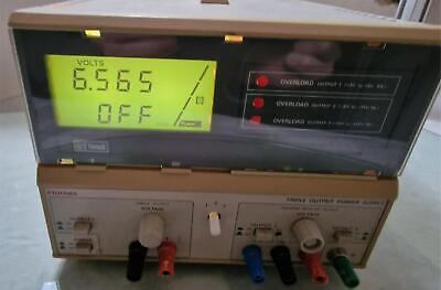
I find having dual outputs quite handy (or two power supplies!) it is very common to have a project with mixed voltages, say 12V and 5V. Beyond that you are likely to buy a switch mode Chinese unit for new in that price bracket - there are lots and lots to choose between! Some little hand held units look neat but I haven't played with them. This would be an example of a bench style Chinese but fair quality unit:


If you don't mind buying used and it being a bit old/odd looking this looks pretty useful:

There are some neat looking little ones on Ali express which might suit you better:
81lVTZML-iL._SL1500_.jpg


Ultimately depends what you want to do and how quiet you need them to be (electrically). I tend to find the larger bench units all round useful because you can use them to charge batteries, power your projects, monitor current etcetc.
 

OEM Battery Nonce

ClioSport Club Member
There are so many to choose from mate and for learning/playing you can't really go wrong!

I find having dual outputs quite handy (or two power supplies!) it is very common to have a project with mixed voltages, say 12V and 5V. Beyond that you are likely to buy a switch mode Chinese unit for new in that price bracket - there are lots and lots to choose between! Some little hand held units look neat but I haven't played with them. This would be an example of a bench style Chinese but fair quality unit:


If you don't mind buying used and it being a bit old/odd looking this looks pretty useful:

There are some neat looking little ones on Ali express which might suit you better:
View attachment 1636934

Ultimately depends what you want to do and how quiet you need them to be (electrically). I tend to find the larger bench units all round useful because you can use them to charge batteries, power your projects, monitor current etcetc.

Thanks Rob,

Are Tenma a decent brand of them? Birthday is Sunday so I'd say we're limited to either Amazon, Farnell or RS at the minute.

Thinking the little bench top is best for now, I have a decent area for it which will be my workspace so doesn't need to be portable.

There are so many Chinese ones on Amazon it's a bit of a minefield and I'd like to get something half decent.
 

Flob

ClioSport Club Member
Thanks Rob,

Are Tenma a decent brand of them? Birthday is Sunday so I'd say we're limited to either Amazon, Farnell or RS at the minute.

Thinking the little bench top is best for now, I have a decent area for it which will be my workspace so doesn't need to be portable.

There are so many Chinese ones on Amazon it's a bit of a minefield and I'd like to get something half decent.
Tenma is not an awful brand - its a known brand if that makes sense. Lots of the Chinese brands I've never heard of. If you pick one and post up a link I don't mind taking a look for you (y)
 

sn00p

ClioSport Club Member
  A blue one.
Gents,

I used to love playing with some circuits and learning electronics when younger so want to pick it up again.

What's a decent desktop power supply for it? Around the £100 mark so nothing too fancy.

It's a birthday present so can't really ask for much over this, and already have most of the other bits and pieces to start knocking things together.

Ps I would pass comment on the above works, but it's so far beyond my ability I'm not sure what I'm looking at 🤣

Love this, honestly it's a really great hobby because with a few components you can make things that do things and you have something tangible.

Seems @Touring_Rob got you on the right path!

I know that it's hard to get over the "Chinese made crap" thing, but they really do crank out decent equipment, they have bought really good quality and well designed equipment will into the range of hobbyists, it's the reason you can buy things like very well specced oscilloscopes for not much outlay now, and they're capable devices.

That said, there is crap out there, but brands like Siglent or Rigol which are Chinese designed & made make some exceptional equipment, to the point that you see that equipment in professional labs all over the place.

Don't be afraid to buy second hand stuff either, you can get bargains. Power supplies are a very good place where this is true, most of the Chinese "supplies" you see aren't really power supplies, technically, they're DC/DC convertors. The big old supplies you see that weight a tonne and you used in school with a couple of analog panel meters are real supplies, they will have a whacking great transformer in them and a variable linear regulator with a heatsink that is the size of the unit and bolted out of the back.

It seems unintuitive that a supply like that, 30 years old, would be better than the flashy one with a graphics display but it will be, it won't have the features like graphing or math functions, but it will provide a very clean and robust rail, the cheap Chinese supplies use a switching regulator to convert from the input voltage to the output, and they can be noisy.

That said, both have their place and the DC/DC probably covers 98% of usage case, but if you can pick up a linear supply for a bargain, it's worth doing.
 

OEM Battery Nonce

ClioSport Club Member
Thanks @sn00p, I'll keep an eye out for second hand stuff going forward and see what comes up.

I went on a spree a few years ago and bought all the current stuff like Arduino, raspberri pi and all sorts of controllers and components but never used them. As silly as it sounds basic power supply was one of the obstacles that I let thwart me so hopefully will overcome that and enjoy playing a bit now.

I've no idea on things to make or try yet though so it'll be an interesting few months of trying to get motivated.

Sorry for the thread hijack, but I'll likely have loads more questions going forward as I try and get electricity to do what I want!


Top