
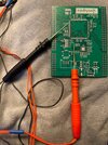
Yet another side project/rabbit hole, although this one was reasonably quick from start to finish, the PCB is being made in china as we speak, so I'm currently using the incredibly hacked together prototype that consists on components on strip board with capacitors and other stuff tacked to legs as I turned the circuit.
Even the prototype with flying wires ,legs in the air has resolution down to 10's of μΩ, no point trying to go beyond that with the prototype since at those kind of numbers moving your hand close to a wire can cause a change, once I have the PCB in hand and everything properly mounted I will see where I stand.
It measures a maximum of 5Ω.
I created this because it's been on my list of "I really should buy a milliohmeter" but "got better things to buy and they're ridiculously expensive for a branded version", which bit me on the ass a few weeks back when I had a short on a board that I couldn't find and I sat there saying "now you wish you'd bought one".
This is where 3D printing really comes into it's own and it's been such a big game changer for me since I can create custom enclosures for stuff, that doesn't look like I'd hacked at an off the shelf design in 1970's beige "project box".
I have actually swapped out the banana sockets on these for normal "instrument ones" (the ones shown here I already had to hand) since they can accept shrouded connectors, although I'm going to replace them with a single aviation connector for a couple of reasons, but the main one being that I need the ability to use point probes rather than standard kelvin clips, and point probes by their very nature will have resistance that needs to be accounted for, with the clips shown here it isn't a problem because the short between force and sense happens at the point if contact of the probe to the resistor, but on a point connector it happens back where the cables are soldered to the probe tip, the resistance from the solder point to the probe tip needs to be accounted for, so using an aviation connector will allow me to house all of connections along side a 1 wire eeprom which the unit can interrogate to retrieve the calibration of the probes.
I'm pretty please with how this project came out.
 . Anyway the strain gauges were using 24bit adc's with a load of tosh for self calibrating out errors from the amplifier, vref and current source, temperature change from environment and self heating was a big problem for them.
 - very cool stuff!
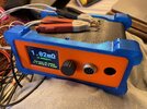
")