

TheBandit
ClioSport Club Member
There is no complete write up on integrating EPAS into a 1*2. As more and more PAS pumps die alternative options will keep these cars on the road. Furthermore there are lots of gripes with third party controllers as they ultimately don't replicate the correct torque maps for the speed you are doing and these may not be sold forever.
I don't claim to be the first person to do this, but I do want to put it on record to help others in the future. Huge thanks to @GrahamS @incy-spider @Taras2016 for the work already done. I run a 1.5 DCi rack and the feeling is spot on, I see no reason why a looped rack won't work but they have been known to flex. With all that preamble out of the way here is the information you are after:
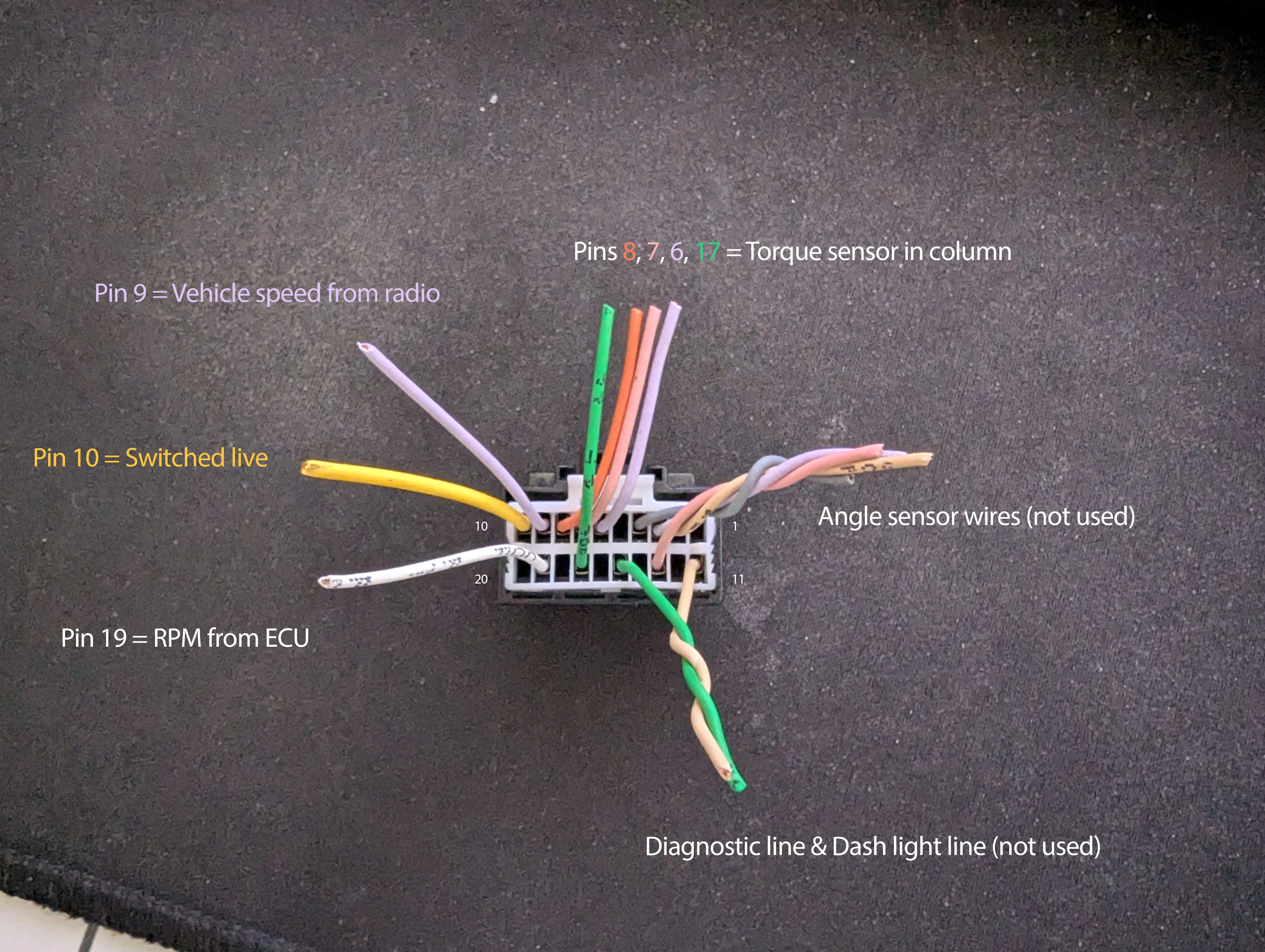
EPAS Control Box Connector
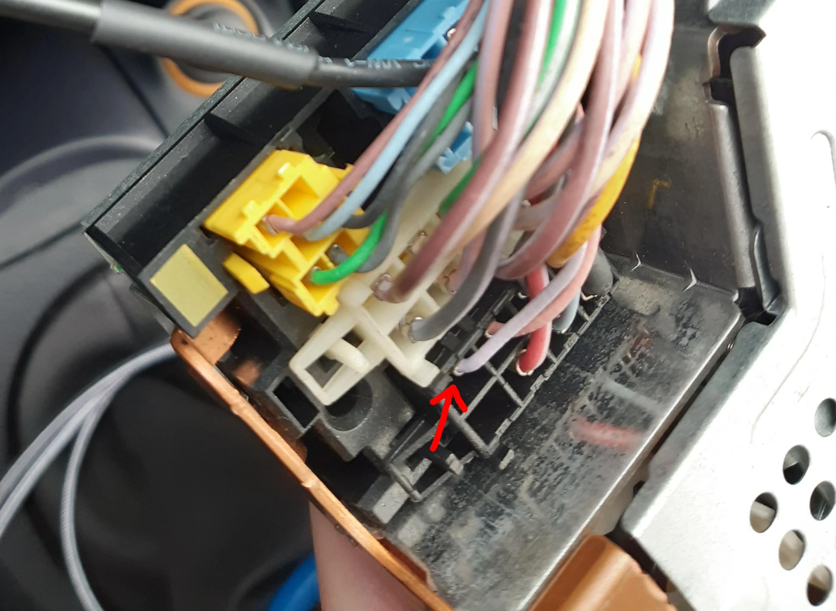
Speed signal taken from Pin 1 on the black connector behind the radio.
Pins 8, 7, 6 and 17 run to the column torque sensor. I work on the basis that any extra information to help the computer adjust the torque map the better. It may work fine without but I personally cannot confirm that.
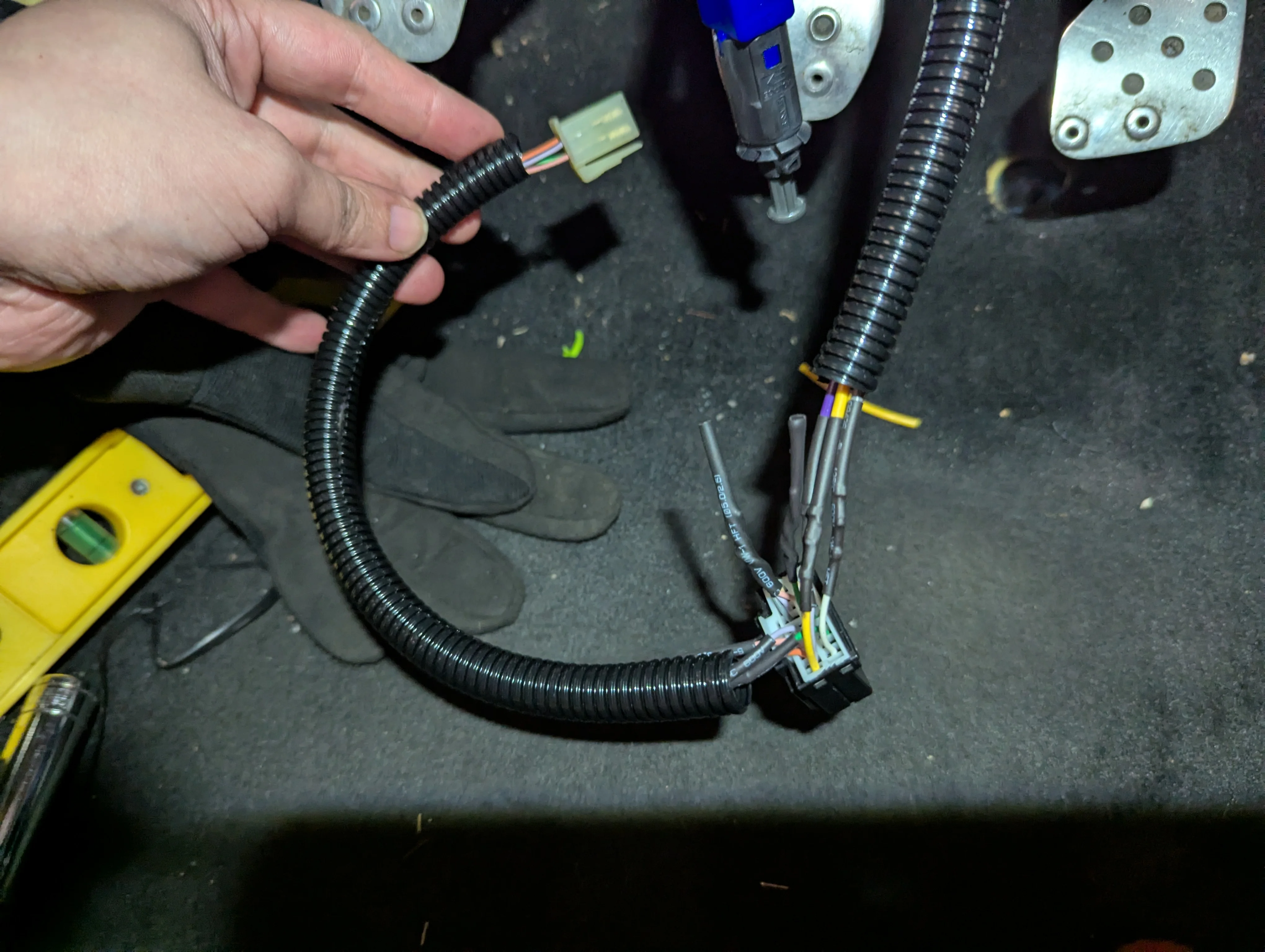
This is the interior side hooked up.
Getting RPM Signal Into The Box
This is the main sticking point, and to date, unrecorded piece of information. Pin 19 from the EPAS control box runs to the two negative coil leads (This includes both cylinder banks for complete RPM reading). This can be taken from the loom wires directly (the two smaller diameter wires are the negatives) or pins 1 and 32 coming out of the ECU. You can connect a multimeter into the coil plug pins and the ECU pins to confirm continuity.
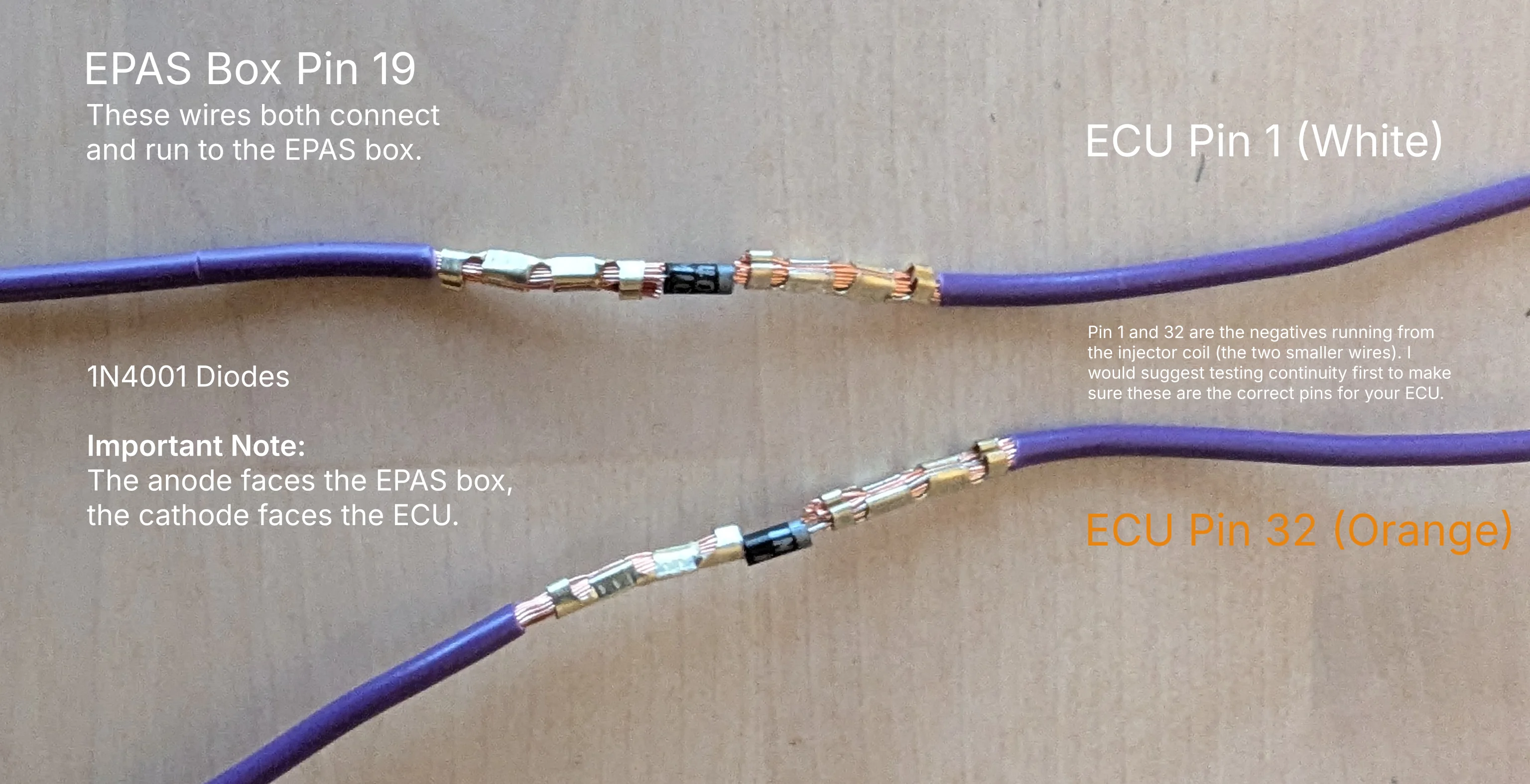
The single EPAS controller wire splits into two connections each with a diode to limit current flow direction. I used 1N4001 diodes with the anode facing the EPAS box and the cathode facing the coils/ECU. This is because the coil returns are negatives.
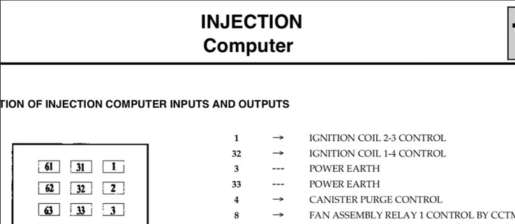
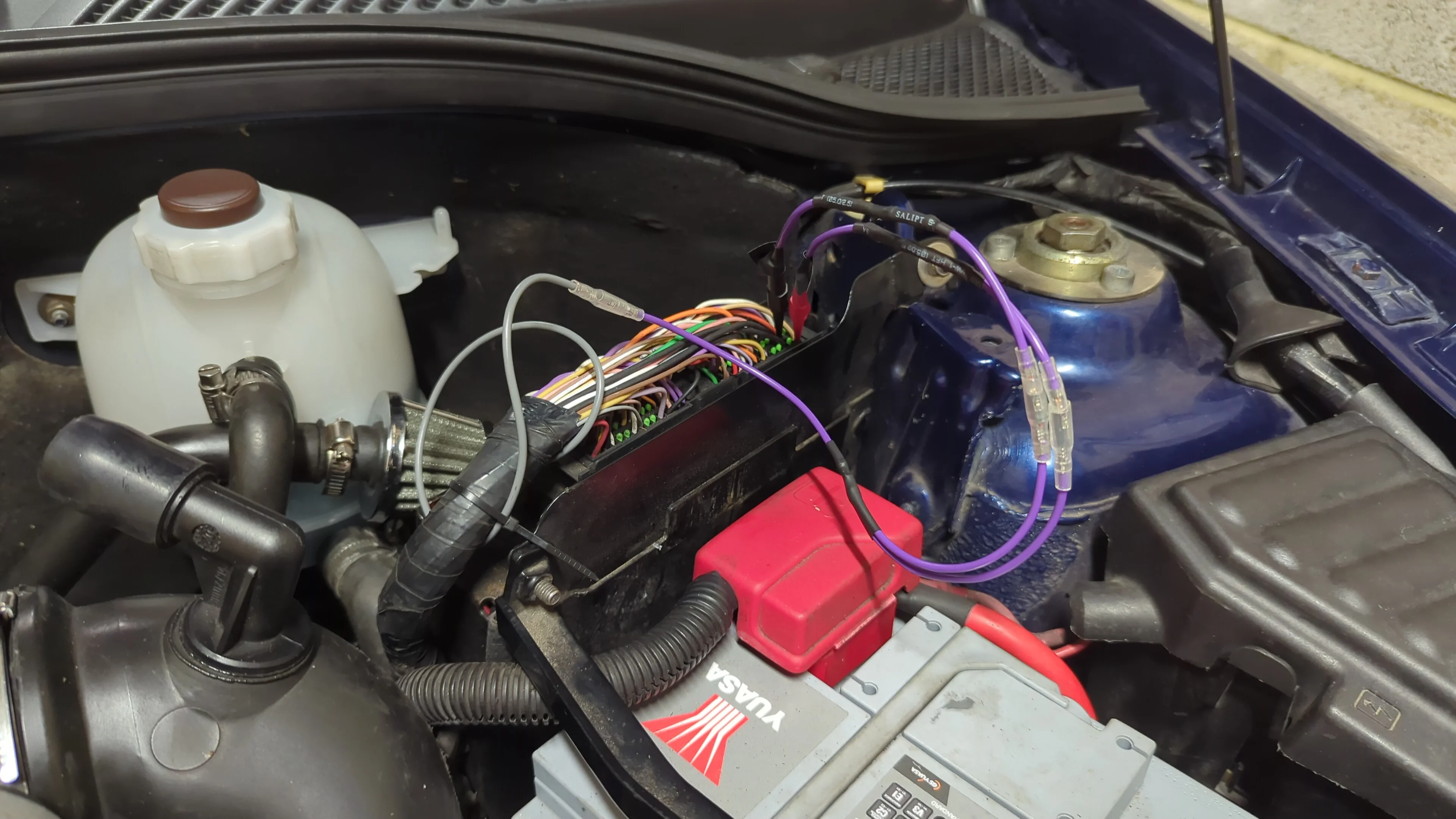
This was my test rig, using probe pins to confirm it worked before crimping into the loom. It's worth noting that the plastic ECU cover is a tight fit so final wiring packaging must be considered.
It's as simple as that! A big thanks again to those that have contributed before. If this could be pinned for future reference that would be amazing - lots of hours went into figuring it all out... especially the diode information that has never been put down in detail. Please leave any questions you may have or more importantly experiences. If you get this working without the torque sensor, or with a looped rack, please share here so others know.
Thanks for reading.
I don't claim to be the first person to do this, but I do want to put it on record to help others in the future. Huge thanks to @GrahamS @incy-spider @Taras2016 for the work already done. I run a 1.5 DCi rack and the feeling is spot on, I see no reason why a looped rack won't work but they have been known to flex. With all that preamble out of the way here is the information you are after:
EPAS Control Box Connector
Speed signal taken from Pin 1 on the black connector behind the radio.
Pins 8, 7, 6 and 17 run to the column torque sensor. I work on the basis that any extra information to help the computer adjust the torque map the better. It may work fine without but I personally cannot confirm that.
This is the interior side hooked up.
Getting RPM Signal Into The Box
This is the main sticking point, and to date, unrecorded piece of information. Pin 19 from the EPAS control box runs to the two negative coil leads (This includes both cylinder banks for complete RPM reading). This can be taken from the loom wires directly (the two smaller diameter wires are the negatives) or pins 1 and 32 coming out of the ECU. You can connect a multimeter into the coil plug pins and the ECU pins to confirm continuity.
The single EPAS controller wire splits into two connections each with a diode to limit current flow direction. I used 1N4001 diodes with the anode facing the EPAS box and the cathode facing the coils/ECU. This is because the coil returns are negatives.
This was my test rig, using probe pins to confirm it worked before crimping into the loom. It's worth noting that the plastic ECU cover is a tight fit so final wiring packaging must be considered.
It's as simple as that! A big thanks again to those that have contributed before. If this could be pinned for future reference that would be amazing - lots of hours went into figuring it all out... especially the diode information that has never been put down in detail. Please leave any questions you may have or more importantly experiences. If you get this working without the torque sensor, or with a looped rack, please share here so others know.
Thanks for reading.


