ClioSport.net

This is a sample guest message. Register a free account today to become a member! Once signed in, you'll be able to participate on this site by adding your own topics and posts, as well as connect with other members through your own private inbox!

  • When you purchase through links on our site, we may earn an affiliate commission. Read more here.

Fan Wiring

Struggler

ClioSport Club Member
Car  Ph1 track 172
Does anyone know how the fan is wired up on these? Not sure there is a difference on the ph1 to the ph2 but I remember reading somewhere there is a connection for low speed and one for high based on AC demand. I basically have this:
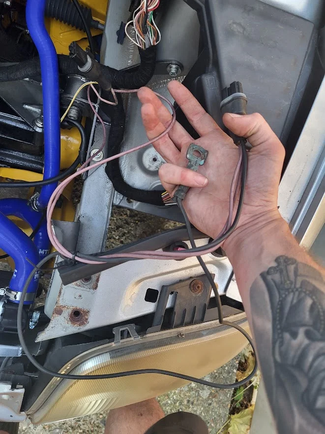
1785395074714.webp
1785395632456.webp


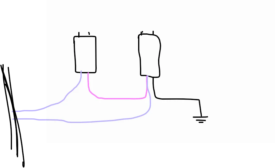
Please enjoy my lovely sketch. But yeh, basically two wires from the loom making three in total if you include the ground. I need to reduce this basically to x2 wires for an aftermarket fan I have but not sure which to take from the main loom and which to cap off.
 
1785439377967.webp

I did a bit of googling and it looks like there's a relay or some kind of connector next to the fan that I can't quote work out what it would do.
 
Unless it sends power via the resistor for a low speed mode and direct to the motor for high speed? 🤔.

I think the low speed mode was for low speed ac performance meaning I could just cap off the wire to the left plug and just keep the other going direct to the right plug.
 
I’m not sure pal. All I remember was in my R53 the resistor pack failed and in order to get it going I used an inline resistor to fix bodge it. Which has probably got naff all to do with your issue 🤐
 
Hey, any input is appreciated! Knowing it's a resistor definitely helps because my theory does make some sense assuming it's just a dumb electric motor running the fan.

I'm not looking to fix anything though, I just want an easy two wires going to my aftermarket fan, that come on when coolant hot and off when coolant not!
 
Super easy mate, done it on my trophy years ago with high powered comex fan. Bin resistor, and run on high power fan/ direct from relay
Awesome! I am also trying to adapt to a comex fan.

1000049439.webp


Would I be right in thinking the plug with two wires going to a single terminal is the fan plug and the other the resistor? As marked up above? And to bin the resistor you just remove the sections I've crossed out?
 
This is ph2 as i dont have a copy of visu for ph1.
Screenshot_20260731_230504_Chrome.webp


777 is 50a fuse in fusebox.
234 is fan relay.
120 is engine ecu/clt sensor.
700 is low speed relay.
321 is ac fan resistor.
262 is rad fan.

Im sure i just removed resistor, and ran pin 2/wire from main relay straight to fan, and other side of fan to earth as oe same as your diagram.
 
That is excellent @Brigsy Thank you! Studying this and my ph1 wiring I believe it looks like this on the ph1:
1786085909542.webp

I am not sure in your image for the ph2 how you would end up getting a different fan power on the low and high speed settings if both are going through the same resistor.

Anyway, the GEN90 ECU I am using i made the wiring ECU pin changes per this chart from Kitson:
1786086113850.webp


This table shows noting in pin 11 which should be earthing the low speed relay (for the AC?), and shows it actually going from PIN8. Perhaps this doesn't matter I am not running AC. It looks like i have correctly moved pin 38 to pin 69 for the main relay. I guess the only way to test now is to short pin 69 to earth and see if the fan pings on!

I had a look at the fan relay as I was wiring it up. it is being controlled by the big yellow one. I assume this is the main fan relay. Not sure which relay is for the low speed (if someone can let me know so I can remove it). I didn't realise the relay was triggered by the earth but did scratch my head why one side was getting 12v and the other seemed to go nowhere, penny dropped when i was laying in bed.
1786086424091.webp
 

Attachments

  • 1786085487896.webp
    1786085487896.webp
    22.5 KB · Views: 1
Sorry, just realised that pin A5 on relay 234 goes to pin 2 on the resistor so doesnt actually go through the resistor. My comment regarding not understanding how you get high power fan on ph2 is void. Interesting that they did it differently on the ph1 and ph2 for seemingly no benefit, maybe ever so shorter wiring? chunky wiring so a bit of a cost save i guess.
 
I had a mate install mine as I was away from home at the time and short on time before an event but I don't recall him mentioning there was much to it. Think it was just a case of lob off the plug and install crimps to suit the terminals on the fan plug
Im away from home and only have a close up photo of the plug so can't provide much info on the wiring
 
No worries, I'm pretty sure I've sorted it. I wasn't sure even which one the fan plug was, since I dumped the fan a while ago during the strip down.

Planning on doing a quick short of ECU pin#69 ;) to ground to confirm the fan comes on then it's another hurdle overcome!
 
Back
Top