ClioSport.net

Register a free account today to become a member!
Once signed in, you'll be able to participate on this site by adding your own topics and posts, as well as connect with other members through your own private inbox!

  • When you purchase through links on our site, we may earn an affiliate commission. Read more here.

Measuring small resistances.


sn00p

ClioSport Club Member
  A blue one.
Yet another side project/rabbit hole, although this one was reasonably quick from start to finish, the PCB is being made in china as we speak, so I'm currently using the incredibly hacked together prototype that consists on components on strip board with capacitors and other stuff tacked to legs as I turned the circuit.

Even the prototype with flying wires ,legs in the air has resolution down to 10's of μΩ, no point trying to go beyond that with the prototype since at those kind of numbers moving your hand close to a wire can cause a change, once I have the PCB in hand and everything properly mounted I will see where I stand.

It measures a maximum of 5Ω.

I created this because it's been on my list of "I really should buy a milliohmeter" but "got better things to buy and they're ridiculously expensive for a branded version", which bit me on the ass a few weeks back when I had a short on a board that I couldn't find and I sat there saying "now you wish you'd bought one".

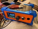
This is where 3D printing really comes into it's own and it's been such a big game changer for me since I can create custom enclosures for stuff, that doesn't look like I'd hacked at an off the shelf design in 1970's beige "project box".

I have actually swapped out the banana sockets on these for normal "instrument ones" (the ones shown here I already had to hand) since they can accept shrouded connectors, although I'm going to replace them with a single aviation connector for a couple of reasons, but the main one being that I need the ability to use point probes rather than standard kelvin clips, and point probes by their very nature will have resistance that needs to be accounted for, with the clips shown here it isn't a problem because the short between force and sense happens at the point if contact of the probe to the resistor, but on a point connector it happens back where the cables are soldered to the probe tip, the resistance from the solder point to the probe tip needs to be accounted for, so using an aviation connector will allow me to house all of connections along side a 1 wire eeprom which the unit can interrogate to retrieve the calibration of the probes.

I'm pretty please with how this project came out.

IMG_5182 2.jpeg
 

Robbie Corbett

ClioSport Club Member
Looks very smart - is this current shunt + amp to get to resistance after calibrating out connectors/leads/tracks etc? Assume so due to the Kelvin connection on the leads.

Very smart looking dude!

I have an HP 34401A which is good for 100uR, so enough for the things I do - I've never actually used it to find shorts on a PCB as I find a high resolution thermal camera is much faster but I do make a several very low resistance coils where knowing the DC resistance is useful.

How do you deal with thermal calibration esp for the current source? just short leads out and run a cal?
 
Last edited:

sn00p

ClioSport Club Member
  A blue one.
Incredible piece of work that! Going to sell them?
No plans too really.

It was more a case of me being able to create something that I know the accuracy and behaviour of against paying the same, or much more, for an off the shelf solution. There's quite a few on AliExpress, but once you start looking at reputable places you start adding zeros to the end of the price.

The ADC in this is impossible to buy at the moment, I had one and I ordered some more this morning, they're supposed to be in stock next month, but whether or not they are is another matter entirely, they're 15 quid each because they have insane specifications, 24-bit no missing codes, they're that accurate that you can trigger multiple ones in sequence from the same input and get the same result, they can only do 8 conversions per second but if you arrange correctly them you can interleave them and get up to 60 conversions per second by using results from all of them.

In my case, 8Hz is fine, there's 3 of them on this board, one is used for the resistance measurement but the other two are used to monitor the voltage drop across the current source resistors to figure out the actual current. These two are really needed, but they allow me to figure out what is happening with the probes (i.e if it's open circuit or in an overload condition), so I can build up the final board using the one I have until the ones I've ordered turn up.

Further to that, the ADC at the top of the current source isn't technically needed since it should always be the reference voltage, but again it allows me to sanity check that the thing is working correctly , if you short the probes together and don't get ~100mA then something is wrong.

And the advantage of the extra ADC's is that it allows me to calibrate the unit automatically and without the need for any outside calibration equipment.
 

sn00p

ClioSport Club Member
  A blue one.
Looks very smart - is this current shunt + amp to get to resistance after calibrating out connectors/leads/tracks etc? Assume so due to the Kelvin connection on the leads.

Very smart looking dude!

I have an HP 34401A which is good for 100uR, so enough for the things I do - I've never actually used it to find shorts on a PCB as I find a high resolution thermal camera is much faster but I do make a several very low resistance coils where knowing the DC resistance is useful.

How do you deal with thermal calibration? just short leads out and run a cal?

4 wire kelvin, so yeah, there's no calibration requirement on the (correctly wired) kelvin "clip type" probes since force/source are connected at the same point, for point probes there is an additional resistance that has to be calibrated out for those specific probes, since I am including an additional resistance from the force/source point to the tip of the probe, I assume you know the answer from your question and mentioning kelvin, but yeah, I pass a known current through the unknown resistance and measure the voltage drop across the same point to calculate the resistance.

I have a HP 34401A as well, the things a utter beast of a unit.

The voltage references I used are temperature compensated, they're always bang on what they should be, the response above gives a little more detail since I use other ADC's to measure other parts of the circuit, I can detect if something is wrong since the only unknown in the circuit is the resistor under test.

I do actually intend to run it over a week or so dumping out raw ADC values and tack a PTC/NTC onto the test resistor and the various chips and capture a whole load of data, I can actually put it in the lounge which seems temperatures go up and down a lot due to there being a stove in there.

I don't have a thermal camera myself, although I'm looking to get one but I'm not exactly what one to get, it's another case I think there the Chinese market is now producing good products to rival the established brands, much in the same way that Siglent and Rigol have definitely eaten away at Tektronix at the "low end' of the market, Siglent are producing incredibly well built, designed and made scopes that would have cost you a fortune not so long back in time.
 

Robbie Corbett

ClioSport Club Member
Nice - how to you compensate for the temperature change of the current source shunt resistor? at 100mA it (they) will change temperature enough to influence the micro ohm scale measurement no? Guessing not by enough to effect the milli ohm readings.

I seem to recall that some commercial instruments chop the current source to avoid heating.

4 wire kelvin, so yeah, there's no calibration requirement on the (correctly wired) kelvin "clip type" probes since force/source are connected at the same point, for point probes there is an additional resistance that has to be calibrated out for those specific probes, since I am including an additional resistance from the force/source point to the tip of the probe, I assume you know the answer from your question and mentioning kelvin, but yeah, I pass a known current through the unknown resistance and measure the voltage drop across the same point to calculate the resistance.

I have a HP 34401A as well, the things a utter beast of a unit.

The voltage references I used are temperature compensated, they're always bang on what they should be, the response above gives a little more detail since I use other ADC's to measure other parts of the circuit, I can detect if something is wrong since the only unknown in the circuit is the resistor under test.

I do actually intend to run it over a week or so dumping out raw ADC values and tack a PTC/NTC onto the test resistor and the various chips and capture a whole load of data, I can actually put it in the lounge which seems temperatures go up and down a lot due to there being a stove in there.

I don't have a thermal camera myself, although I'm looking to get one but I'm not exactly what one to get, it's another case I think there the Chinese market is now producing good products to rival the established brands, much in the same way that Siglent and Rigol have definitely eaten away at Tektronix at the "low end' of the market, Siglent are producing incredibly well built, designed and made scopes that would have cost you a fortune not so long back in time.
The voltage reference for the ADC's? I guess this and the shunt resistor (for measuring current through the load) are the two main sources of error? I made a fairly high res capacitance meter a few years ago and had known reference that got switched in occasionally to zero everything.

Was sitting here trying to figure out if you could do this with a 16bit adc and the answer is no, not really - at least not without either dropping the Vref to something unpractical (target 100uR measurement) or adding an amplifier which would become another source of error (although some zero-drift opamps are very good).

I like to the little ADS range of adc's, the 1115 is a 4channel, or 2channel differential - 16bit but don't have the option of an external Vref.

Agree on the test equipment front, wonder how much that will change with the US blocking tech to China - although Rigol for example have some impressive equipment now, low noise scopes etc I just can't get on with them compared to Tek scopes their user interface is very tedious.

You would have some good chats with my dad - a few years back he was doing a large strain gauge project for a large telescope in Hawaii. They split the dish up into lots of little plates and then needed to measure the strain on each plate so they could calculate error/offset. Changing shape by 0.001mm seems to be a problem when you are looking at things a million light years away - assume each plate was an antenna but 🤷‍♂️ . Anyway the strain gauges were using 24bit adc's with a load of tosh for self calibrating out errors from the amplifier, vref and current source, temperature change from environment and self heating was a big problem for them.

Cheers for posting this up Snoop, its been a geeky and enjoyable distraction for me as I've got a killer headache today.
 

sn00p

ClioSport Club Member
  A blue one.
Nice - how to you compensate for the temperature change of the current source shunt resistor? at 100mA it (they) will change temperature enough to influence the micro ohm scale measurement no? Guessing not by enough to effect the milli ohm readings.

I seem to recall that some commercial instruments chop the current source to avoid heating.


The voltage reference for the ADC's? I guess this and the shunt resistor (for measuring current through the load) are the two main sources of error? I made a fairly high res capacitance meter a few years ago and had known reference that got switched in occasionally to zero everything.

Was sitting here trying to figure out if you could do this with a 16bit adc and the answer is no, not really - at least not without either dropping the Vref to something unpractical (target 100uR measurement) or adding an amplifier which would become another source of error (although some zero-drift opamps are very good).

I like to the little ADS range of adc's, the 1115 is a 4channel, or 2channel differential - 16bit but don't have the option of an external Vref.

Agree on the test equipment front, wonder how much that will change with the US blocking tech to China - although Rigol for example have some impressive equipment now, low noise scopes etc I just can't get on with them compared to Tek scopes their user interface is very tedious.

You would have some good chats with my dad - a few years back he was doing a large strain gauge project for a large telescope in Hawaii. They split the dish up into lots of little plates and then needed to measure the strain on each plate so they could calculate error/offset. Changing shape by 0.001mm seems to be a problem when you are looking at things a million light years away - assume each plate was an antenna but 🤷‍♂️ . Anyway the strain gauges were using 24bit adc's with a load of tosh for self calibrating out errors from the amplifier, vref and current source, temperature change from environment and self heating was a big problem for them.

Cheers for posting this up Snoop, its been a geeky and enjoyable distraction for me as I've got a killer headache today.

Ha, no worries, I thought it might be of interest to a few peeps in here.

Yeah, 16-bit won't cut the mustard!

The actual "sense" measurement is taken with a 24-bit ADC operating in single ended mode, the reason being that it's fed from (what was a burr brown) differential precision fixed gain op-amp.

Funnily enough in the prototype hardware I actually have and ADS1115 operating in differential mode but that's purely to measure the drop across the resistors in the current source, of which there are 4 x 0.01% tolerance of them in parallel, so each resistor is carrying 25mA, and they're big, massive, they occupy nearly 1/4 of of the board.

Now the reason for the ADS1115 is simple, I couldn't get any more more of the 24-bit ADC, they're out of stock everywhere (as they have been for the past few years), so I had to make do with the one.

In the actual layout, there's 3, but for a working unit only 1 is required with calibration. In the prototype I used the ADS1115 to monitor the top of the current sense resistors, the arrangement is using a precision constant current source and a dedicated precision voltage reference to create the 100mA source, crucially the constant current source and the ADC use different voltage references. The ADC1115 is being used in differential mode to measure the drop across the CCS resistors, so I know.

1.) What the exact voltage is being used for the constant current source (and therefore the sense voltage).
2.) The drop across the sense resistors.

So at any given point in time, I know exactly what the current was at the time of that the sense measurement was taken.

I mentioned in a previous post that I don't currently use this in a useful way, since in the real PCB all 3 ADC's will be triggered at the same time, I can't do that at the moment because that's not possible, so I trigger the ADS1115 and the LTC ADC slightly after each other.

In the current firmware, it uses the ADS1115 measurement as a means to detect "OPEN" and "OVERLOAD" conditions, with the caveat that there's an EDGE case for OPEN/OVERLOAD where out of range readings result in me measuring a lower force current, so I can display OVERLOAD up until the current measurement has dropped to zero, at which case it displays OPEN since as far as it's concerned it is OPEN, so currently I'm using the measurement purely to gate "OPEN"/"OVERLOAD"/"actual measurement result".

Because the current source and ADC have different voltage references then I can further sanity check that things are correct, i.e if I don't see the right voltage at the top of the CCS then something is wrong, since the ADC and CCS have different references one or the other has a fault if it's not correct.

I have an order for more ADC's, I'm not holding out hope for them actually arriving next month, but we'll see. But with those in circuit I can simultaneusly measure the current at the exact time that the sense measurement is taken, I can then use that in the calculation in real time.
 

sn00p

ClioSport Club Member
  A blue one.
btw, the 24-bit ADC is actually 28 bit, but they qualify it as a 24-bit ADC and that the lowest 4 bits are actually sub codes, you ignore them unless you want to make use of them in averaging, it's not described as a 28-bit ADC, it's somewhat of a surprise to find that's what it actually is when you read the data sheet.

Also, the temperature of the resistor under test will have an effect on measurement, although moving the clip position fractional parts of a mm also affects it since we're measuring stuff in microohms.

I have actually left it for 12 or so hours and glanced at it every so often and it's always remained on the same number.
 

sn00p

ClioSport Club Member
  A blue one.
Nice - how to you compensate for the temperature change of the current source shunt resistor? at 100mA it (they) will change temperature enough to influence the micro ohm scale measurement no? Guessing not by enough to effect the milli ohm readings.

I seem to recall that some commercial instruments chop the current source to avoid heating.


The voltage reference for the ADC's? I guess this and the shunt resistor (for measuring current through the load) are the two main sources of error? I made a fairly high res capacitance meter a few years ago and had known reference that got switched in occasionally to zero everything.

Was sitting here trying to figure out if you could do this with a 16bit adc and the answer is no, not really - at least not without either dropping the Vref to something unpractical (target 100uR measurement) or adding an amplifier which would become another source of error (although some zero-drift opamps are very good).

I like to the little ADS range of adc's, the 1115 is a 4channel, or 2channel differential - 16bit but don't have the option of an external Vref.

Agree on the test equipment front, wonder how much that will change with the US blocking tech to China - although Rigol for example have some impressive equipment now, low noise scopes etc I just can't get on with them compared to Tek scopes their user interface is very tedious.

You would have some good chats with my dad - a few years back he was doing a large strain gauge project for a large telescope in Hawaii. They split the dish up into lots of little plates and then needed to measure the strain on each plate so they could calculate error/offset. Changing shape by 0.001mm seems to be a problem when you are looking at things a million light years away - assume each plate was an antenna but 🤷‍♂️ . Anyway the strain gauges were using 24bit adc's with a load of tosh for self calibrating out errors from the amplifier, vref and current source, temperature change from environment and self heating was a big problem for them.

Cheers for posting this up Snoop, its been a geeky and enjoyable distraction for me as I've got a killer headache today.

Just as an aside, since you're clearly into this geeky stuff (although this is probably more on the nerdy side).

CERN released the design that they use on the LHC for a 8 1/2 digit volt meter... I watched a video on it late last year and some guy built one!

Not for the feint hearted. Not sure how much it cost him to build it either, but it has machined heatsinks, pelters (I actually considered a Peltier in this project!)


I just flicked though it and I remember wincing at his vapour phase "oven", we have a vapour phase oven and galdon is f**king expensive so the oven basically has a whole load of stuff inside it to condense it back and retrieve all the fluid and store it back safely in the tank, he literally uses a couple of book clips and a sheet of glass to do it, I hate to think how much fluid he lost.
 

Robbie Corbett

ClioSport Club Member
Just as an aside, since you're clearly into this geeky stuff (although this is probably more on the nerdy side).

CERN released the design that they use on the LHC for a 8 1/2 digit volt meter... I watched a video on it late last year and some guy built one!

Not for the feint hearted. Not sure how much it cost him to build it either, but it has machined heatsinks, pelters (I actually considered a Peltier in this project!)


Did you imagine I hadn't already watched that 🤣 - very cool stuff!

He's got some other really nice videos on voltage references etc. Its worth keeping an eye on eBay, occasionally an oven compensated voltage reference will come up and they are really neat - in a little enclosure with the heater etc inside, they don't seem to be nearly as common as oven compensated oscillators.

PS - I have one of these:
1675197128173.png


And agree the Galden is properly expensive stuff! Suspect he got it for free though and if you were willing to let it cool for long enough you probably don't lose a terrible amount.
 
Last edited:

Robbie Corbett

ClioSport Club Member
btw, the 24-bit ADC is actually 28 bit, but they qualify it as a 24-bit ADC and that the lowest 4 bits are actually sub codes, you ignore them unless you want to make use of them in averaging, it's not described as a 28-bit ADC, it's somewhat of a surprise to find that's what it actually is when you read the data sheet.

Also, the temperature of the resistor under test will have an effect on measurement, although moving the clip position fractional parts of a mm also affects it since we're measuring stuff in microohms.

I have actually left it for 12 or so hours and glanced at it every so often and it's always remained on the same number.
If it's stable over 12 hours I think you've won!

Another useful little box I've been meaning to make forever (therefore probably never will) is an ammeter that can measure micro amps, or a programmable power supply that can measure current down to that level.

We had a very low power project a while back and a convenient high resolution current meter would have been very handy.
 

sn00p

ClioSport Club Member
  A blue one.
If it's stable over 12 hours I think you've won!

Another useful little box I've been meaning to make forever (therefore probably never will) is an ammeter that can measure micro amps, or a programmable power supply that can measure current down to that level.

We had a very low power project a while back and a convenient high resolution current meter would have been very handy.

I bought this a year or two back:


The back story to this is that I created a humidity monitor for filament dry boxes for 3D printer spools (I'm pretty sure I posted about this), it used an ESP32 and a e-paper display since this allowed me to display the "current" status of a given box, it published data to a MQTT server but having a display meant that I also could just glance at a box, if I saw a massive red message I knew there was some issue.

The device woke up twice an hour, updated the display and published to MQTT, with the LIPO cell I was using this meant a 2 month runtime between charges, in reality that could be extended by a massive amount, twice an hour is overkill and I could just avoid any updates outside of when I was awake, I think with not much effort I could extend that probably to a year or more between charges.

I designed the thing to run as frugal as possible, the regulator I used was super low quiescent current, I stuck an RTC on just to stop me needing to query NTP, potentially saving seconds while it was woken up, it uses freertos and multiple threads to try and get stuff done in parallel since there was a few places where I could streamline it before eventually waiting for things to come back together.

In deep sleep I could get the board down to 12nA, but without being able to measure it I actually had no idea since that is so low nothing I had could measure that, so I looked around and bought the current ranger.

The problem is that the device goes from nA to mA to 100's mA very quickly and the ESP32 is notoriously difficult to measure since this involves range changes from nA to mA, which means the device that's performing the measurement has to be able to auto range and it needs to be able to auto range fast enough so that the device under test doesn't get a power interruption or brownout, and without going to extremes like a keithley meter, this seemed to be the only real choice. There's also one by somebody else, a chip vendor, but I can't remember who it is that I think is about 80 quid or so and I've seen people have success with that, but I bought the CurrentRanger and it hasn't skipped a beat.

I had a hard time getting hold of regulators though, I took a punt on some from AliExpress and when they turned up I built up a board and discovered that my newly built one was consuming 70-80nA, basically 7 times more than it should and as ridiculous as is sounds when you're talking about 11nA vs 70nA, in my case this reduced the runtime by 7 times. I ended up removing a few bits, initially I thought it was the ESP32 because I'd bought 16MiB modules and my prototype had 4MiB, but eventually I removed the regulator from my original prototype and put it on the newly build board and the current dropped to the correct level.

So I then took a sample of regulators from various points on the the tape and they all were terrible (relatively speaking), so I filed them in the bin and ended up having to buy hundreds of them from DigiKey in the USA since they were the only place with stock, I now have enough low power regulators to last me for many years to come!

So TLDR; The Current Ranger is a great bit of kit. The firmware is open-source and the design is also posted, but the one I bought is very high quality and in the end it was just the easiest solution, the guy had done all the hard work and it's not that expensive,
 

sn00p

ClioSport Club Member
  A blue one.
I've also printed out another case section (8 hour print!) and bumpers except in blue this time, I'm going to quickly knock up a board with various precision reference outputs with an input as well, same LCD as on this I'll show the reference voltages but also the differential between a specific reference and the input, which will be useful for monitoring ADC's on other boards and also for suppling a known good reference to a circuit during development.

Very noddy PCB, but should be useful.
 

Robbie Corbett

ClioSport Club Member
I bought this a year or two back:


The back story to this is that I created a humidity monitor for filament dry boxes for 3D printer spools (I'm pretty sure I posted about this), it used an ESP32 and a e-paper display since this allowed me to display the "current" status of a given box, it published data to a MQTT server but having a display meant that I also could just glance at a box, if I saw a massive red message I knew there was some issue.

The device woke up twice an hour, updated the display and published to MQTT, with the LIPO cell I was using this meant a 2 month runtime between charges, in reality that could be extended by a massive amount, twice an hour is overkill and I could just avoid any updates outside of when I was awake, I think with not much effort I could extend that probably to a year or more between charges.

I designed the thing to run as frugal as possible, the regulator I used was super low quiescent current, I stuck an RTC on just to stop me needing to query NTP, potentially saving seconds while it was woken up, it uses freertos and multiple threads to try and get stuff done in parallel since there was a few places where I could streamline it before eventually waiting for things to come back together.

In deep sleep I could get the board down to 12nA, but without being able to measure it I actually had no idea since that is so low nothing I had could measure that, so I looked around and bought the current ranger.

The problem is that the device goes from nA to mA to 100's mA very quickly and the ESP32 is notoriously difficult to measure since this involves range changes from nA to mA, which means the device that's performing the measurement has to be able to auto range and it needs to be able to auto range fast enough so that the device under test doesn't get a power interruption or brownout, and without going to extremes like a keithley meter, this seemed to be the only real choice. There's also one by somebody else, a chip vendor, but I can't remember who it is that I think is about 80 quid or so and I've seen people have success with that, but I bought the CurrentRanger and it hasn't skipped a beat.

I had a hard time getting hold of regulators though, I took a punt on some from AliExpress and when they turned up I built up a board and discovered that my newly built one was consuming 70-80nA, basically 7 times more than it should and as ridiculous as is sounds when you're talking about 11nA vs 70nA, in my case this reduced the runtime by 7 times. I ended up removing a few bits, initially I thought it was the ESP32 because I'd bought 16MiB modules and my prototype had 4MiB, but eventually I removed the regulator from my original prototype and put it on the newly build board and the current dropped to the correct level.

So I then took a sample of regulators from various points on the the tape and they all were terrible (relatively speaking), so I filed them in the bin and ended up having to buy hundreds of them from DigiKey in the USA since they were the only place with stock, I now have enough low power regulators to last me for many years to come!

So TLDR; The Current Ranger is a great bit of kit. The firmware is open-source and the design is also posted, but the one I bought is very high quality and in the end it was just the easiest solution, the guy had done all the hard work and it's not that expensive,
I like it!
 

sn00p

ClioSport Club Member
  A blue one.
Haha, I’m a bit humbled that this has has piqued people’s interest.

When the proper PCB arrives I’ll be able to see how far I can push this hardware, I may consider just releasing the hardware design and code, there’s a few expensive (well relatively) parts on it that currently can’t be bought anywhere, I’m hoping that by the end of this year the component market might be approaching sanity again, we are seeing things easing a bit now.

I have stuck a bigger LCD on it, same resolution but it looks better proportioned in the case, the front panel is now bevelled with the LCD which makes a huge difference. I’ve also added a rotary encoder on the front and replaced the banana jacks with an aviation connector since it allows me to add an EEPROM in the cable to store calibration data for point probes, although if you’re only interested in measuring resistances then it’s not required since the 4 wire kelvin method doesn’t need it if force and sense are shorted in the resistor under test.

I’m working through ideas on a four wire probe (force & sense are separated and only short on contact to the board), I have a few ideas but it’s not high on my list of things to do, I am concentrating on the firmware for the moment.

You can see on this the raw voltage reading on the ADC displayed under the measurement, this ADC is insane, I actually have two of its 16-bit siblings which I will try this week.

Picture of the point probes as well, but as I said, these require calibration since the shift between force and sense happens at the bottom of the needle, so the resistance from that point to the tip on both probes ends up being measured, I have a notion of 4 needles (2 per probe) arranged in a V, trying to get the points as close as possible without shorting, relying on the short st the point of contact.
 

Attachments

  • 7D11D52C-1217-48F2-B62D-DCD78CB372B1.jpeg
    7D11D52C-1217-48F2-B62D-DCD78CB372B1.jpeg
    3.2 MB · Views: 52
  • 9C39470B-FDF3-4ACD-8192-7D66B4EA3075.jpeg
    9C39470B-FDF3-4ACD-8192-7D66B4EA3075.jpeg
    524.2 KB · Views: 48

Robbie Corbett

ClioSport Club Member
Haha, I’m a bit humbled that this has has piqued people’s interest.

When the proper PCB arrives I’ll be able to see how far I can push this hardware, I may consider just releasing the hardware design and code, there’s a few expensive (well relatively) parts on it that currently can’t be bought anywhere, I’m hoping that by the end of this year the component market might be approaching sanity again, we are seeing things easing a bit now.

I have stuck a bigger LCD on it, same resolution but it looks better proportioned in the case, the front panel is now bevelled with the LCD which makes a huge difference. I’ve also added a rotary encoder on the front and replaced the banana jacks with an aviation connector since it allows me to add an EEPROM in the cable to store calibration data for point probes, although if you’re only interested in measuring resistances then it’s not required since the 4 wire kelvin method doesn’t need it if force and sense are shorted in the resistor under test.

I’m working through ideas on a four wire probe (force & sense are separated and only short on contact to the board), I have a few ideas but it’s not high on my list of things to do, I am concentrating on the firmware for the moment.

You can see on this the raw voltage reading on the ADC displayed under the measurement, this ADC is insane, I actually have two of its 16-bit siblings which I will try this week.

Picture of the point probes as well, but as I said, these require calibration since the shift between force and sense happens at the bottom of the needle, so the resistance from that point to the tip on both probes ends up being measured, I have a notion of 4 needles (2 per probe) arranged in a V, trying to get the points as close as possible without shorting, relying on the short st the point of contact.
How much does it matter measuring tip resistance + load? Won't calibrate out reliability?
 

sn00p

ClioSport Club Member
  A blue one.
How much does it matter measuring tip resistance + load? Won't calibrate out reliability?

it’s not a massive issue since in reality with point proves you’re measuring in a relative way, you are measuring across a two nets (vcc and GND) to find the smallest value, since you probe across components if the value goes up, you’re moving away from the short, you’re always going in the direction that yields the smallest value.

so it doesn’t matter a huge amount whether there’s an additional 10 milliohms or not, but, it does make it easy to know when you’re right on the money since if it’s microohms on screen then it’s clearer than say 10 milliohms + 80 microohms.

the point tips themselves have a resistance of around 2 milliohms (each), which is an order of magnitude bigger than my resolution.

That said, I have a solution for 4 wire “nearly” point proves, I built one probe last night but I’m away now until Sunday, so I’ll build the second one then and test, but this maintains the 4 wire advantage and therefore without adding any extra resistance.
 

sn00p

ClioSport Club Member
  A blue one.
I’m not unsurprising news, here’s the first push back, from 1st March to 8th of May….

I’m not entirely hopeful on the new date.
001611B5-4DB6-42EB-91D0-EE97645F890C.jpeg
 
Last edited:

sn00p

ClioSport Club Member
  A blue one.
My mum is unwell at the moment, we're staying with her and to keep my mind occupied I did a load more changes to the hardware.

I've added a bunch of FETs to allow me to perform calibration without interaction from the user, I can now disconnect the force sense cables and I'm now able to internally short force/sense (intentionally) in isolation which allows me to (re)calibrate on the fly, I have a load of FETs with a very low RDS(on) but assuming all these changes work, I will be able to find ones with an even lower RDS(on).

I've also added secondary 16-bit ADC's which can be fitted in place of the 24-bit ones for the calibration, same family as the 24-bit, the 16-bit ones though do have programmable gain, these should be more than sufficient for measuring "zero" on force and sense, although I can fit either, the 16-bit ones seem to be reasonably easy to buy.

I'm tempted to add a second op-amp stage on the sense, but I'll decide on that once I've got the the Rev. 1 board built up since I can then gauge noise, I can always tack on the second stage to the Rev. 1 board to get a better idea of performance.

The lead time on the 24-bit ADC has changed again, it's now back to march, I imagine it's going to flip flop around quite a bit over the next month or so.

Milliohmeter.png
 

Robbie Corbett

ClioSport Club Member
Sorry to hear about your mum.

Changes look great! I'm finding lead times are changing on a near daily basis, even though the situation has improved a lot over 6months ago.

Last time you posted about the ADC I did some very rough maths and recon you could achieve good results with a 16bit ADC and a good amplifier, but I suspect you are pushing for ultimate performance (and why not).

If I could make a small suggestion it would be to switch out mosfets for relays for the cal loopbacks. RDS changes quite drastically between fets and with temperature etc etc. Lots of electrolytic caps but not too many ceramics?
 

sn00p

ClioSport Club Member
  A blue one.
Sorry to hear about your mum.

Changes look great! I'm finding lead times are changing on a near daily basis, even though the situation has improved a lot over 6months ago.

Last time you posted about the ADC I did some very rough maths and recon you could achieve good results with a 16bit ADC and a good amplifier, but I suspect you are pushing for ultimate performance (and why not).

If I could make a small suggestion it would be to switch out mosfets for relays for the cal loopbacks. RDS changes quite drastically between fets and with temperature etc etc. Lots of electrolytic caps but not too many ceramics?
I knew you'd ask that!

And yeah, I've considered it, I can probably squeeze in a header to an external relay and put solder bridge jumpers (NC, i.e not using relay) to select between them, there are solder bridges there that allow me to bypass the FET's anyway since I don't know the exact performance of them and if it's s**t, I can revert the circuit by bridging the solder jumpers. The RDS(on) of the FET I have to hand and will be using for tests quotes a max difference of 10 uOhm across the range from 25 to 125 degrees celcius according to the data sheet. Reality might be different though, I will test a few to see what they're actually like in comparison to each other.

Not all those electrolytic caps are in use, they're there to allow me to add and additional caps near to the relevant pins, nominally it's spaced for a 5mm electrolytic so there's enough space to actually physically fit one, but I could fit a ceramic or tantalum in those extra positions, if I'd used a ceramic as a placeholder I'd have to make sure there was enough space to fit an electrolytic, and I guarantee I'd forget and end up putting them too close, just easier to say they're electrolytic since I then I know the polarity if I need to fit a electrolytic or tantalum.

The op-amp on this is a beast of a device, it's burr-brown part that TI inherited when they bought burr-brown, it's a very nice device, I am tempted to put a second stage op-amp as well, I would probably feed that into a 16-bit ADC, of course while I am at it it would probably make sense to do as I did on the calibration section and add a 16-bit ADC on the underside of the PCB under the 24-bit one, I can then choose which to fit, I definitely can't fit a 16-bit on the top side since there's zero space.

It's reached a point where it's way beyond what I need already, but I can use it to properly test the various chips on this, because there's a load of other bits of kit that these parts could be used in.

I absolutely foresee creating something with a LTZ1000A reference in the near future, possibly a silly volt meter, for no other reason than that reference being nuts.

The Rev. 1 board that I'm waiting for PCB's is a lot more barebones than the current design, but it gives me an absolute first benchmark of the core design since it's currently strip board, a lot of flying wires, loads of components tacked to legs, horrible connections to ground/vcc/references, so it should be much better....

I can build up various portions of the Rev. 2 design and tack onto the Rev. 1 PCB to see if they will work in practice and not just as a design or idea in my head.
 

Robbie Corbett

ClioSport Club Member
The LTZ1000A kits you can get look like a cheap way to build a very nice reference the LTZ being the most expensive part naturally!

There is also talk of the ADR1000 however that seems to be unobtanium. Worth taking a look at the LM399 which isn't as awesome but is substantially cheaper.

PS - LTC2057 is worth a look in for your milliohm project - not sure how it stacks up compared to the BB you are using. LTC2057 but these chopper amps do really well with regard to 1/f noise as well as temp stability.
 

sn00p

ClioSport Club Member
  A blue one.
PS - LTC2057 is worth a look in for your milliohm project - not sure how it stacks up compared to the BB you are using. LTC2057 but these chopper amps do really well with regard to 1/f noise as well as temp stability.
That's a very good op-amp, so good on paper that I've decided modify the finished R2 design and replace the BB op-amp since I can then do comparisons, everything in GIT so it's easy to revert back.

nearly every part of analog design is using LT parts now, apart from a rail generator for +/- on the opamp rails.

with this new opamp I need two of them and the LT1991 as per the opamp datasheet application note for a precise differential amp, the LT1991 can have gain as well.

I've also added a 1.27mm connector which can be bought in circuit (it’s out of circuit by default to avoid creating trace stubs) and provides the necessary signals that allow relays to be used for auto calibration, depending on solder bridge states and fitted components I can now have no provision for auto calibration or the option of auto calibration using FET's or relays.

I have bought a few Vishay dale resistors as well for testing since I know they’re most definitely accurate, the Chinese ones seem remarkably good but it’s difficult to accurately measure.

I need to buy a few more, I’ll then create a “standards box” with known resistances with the added microohms introduce with the internal wiring - good job I have a milli

i’ll upload a video later with the current hardware and a vishay resistor.

back from my mums, I have a load of my own hospital appointments next week, but I think I’ll be back there very soon as she really is not very well, projects like this are a welcome distraction, even modifying the Rev 2 design in KiCad over the past few days with the relay and opamp kept my brain occupied on stuff other than overthinking my mums health.
 

Robbie Corbett

ClioSport Club Member
That's a very good op-amp, so good on paper that I've decided modify the finished R2 design and replace the BB op-amp since I can then do comparisons, everything in GIT so it's easy to revert back.

nearly every part of analog design is using LT parts now, apart from a rail generator for +/- on the opamp rails.

with this new opamp I need two of them and the LT1991 as per the opamp datasheet application note for a precise differential amp, the LT1991 can have gain as well.

I've also added a 1.27mm connector which can be bought in circuit (it’s out of circuit by default to avoid creating trace stubs) and provides the necessary signals that allow relays to be used for auto calibration, depending on solder bridge states and fitted components I can now have no provision for auto calibration or the option of auto calibration using FET's or relays.

I have bought a few Vishay dale resistors as well for testing since I know they’re most definitely accurate, the Chinese ones seem remarkably good but it’s difficult to accurately measure.

I need to buy a few more, I’ll then create a “standards box” with known resistances with the added microohms introduce with the internal wiring - good job I have a milli

i’ll upload a video later with the current hardware and a vishay resistor.

back from my mums, I have a load of my own hospital appointments next week, but I think I’ll be back there very soon as she really is not very well, projects like this are a welcome distraction, even modifying the Rev 2 design in KiCad over the past few days with the relay and opamp kept my brain occupied on stuff other than overthinking my mums health.
Will make a better reply later, just dealing with kiddo. I may have a better suggestion for LT1991 but need to dig through some older designs to find it (can't remember the pt.no).

The 1991 has nice offset specs but they don't shout about noise performance too much, with the large internal value series resistors its not going to have outstanding input referred noise which might cause you problems - rather cost you resolution if/when you crank up the gain. You'll want some filtering on the output for sure and you are in the nice position of not requiring very high sampling frequencies.

*Edit noise performance actually isn't terrible but not as good as the input amplifiers - so adding as much gain to those as possible and running less gain at the 1991 is probably favourable.

Sorry about your mum - how old is she?
 

sn00p

ClioSport Club Member
  A blue one.
Will make a better reply later, just dealing with kiddo. I may have a better suggestion for LT1991 but need to dig through some older designs to find it (can't remember the pt.no).

The 1991 has nice offset specs but they don't shout about noise performance too much, with the large internal value series resistors its not going to have outstanding input referred noise which might cause you problems - rather cost you resolution if/when you crank up the gain. You'll want some filtering on the output for sure and you are in the nice position of not requiring very high sampling frequencies.

*Edit noise performance actually isn't terrible but not as good as the input amplifiers - so adding as much gain to those as possible and running less gain at the 1991 is probably favourable.

Sorry about your mum - how old is she?

I'm not using the gain on the 1991, it's configured for 1:1 purely to convert the differential signal to a single ended for the ADC, even on the op-amp stage I'm only running with x10 gain, the BB opamp I was using was a fixed gain one, I can at least now modify the gain on the op-amps with the one you suggested.

I do now however have to fit good resistors on the opamp circuit with a good TC and tolerance since with the BB part, these were internal to the op-amp and laser trimmed so it wasn't a concern for me.

I have had one of the Vishay 50 mOhm resistors connected to the prototype since 2pm and it's sat on 50 mOhm all day, with a +- of 0.01mOhm, which I'm pretty pleased with considering just how hacked together the internals are, there is no averaging at all either, it updates the screen when there's a new acquisition.

No rush on the LT1991 alternative, I'm about to crash for tonight, I'm so tired from everything that's happened this past week.

Mum is 82.
 

Robbie Corbett

ClioSport Club Member
Will make a better reply later, just dealing with kiddo. I may have a better suggestion for LT1991 but need to dig through some older designs to find it (can't remember the pt.no).

The 1991 has nice offset specs but they don't shout about noise performance too much, with the large internal value series resistors its not going to have outstanding input referred noise which might cause you problems - rather cost you resolution if/when you crank up the gain. You'll want some filtering on the output for sure and you are in the nice position of not requiring very high sampling frequencies.

*Edit noise performance actually isn't terrible but not as good as the input amplifiers - so adding as much gain to those as possible and running less gain at the 1991 is probably favourable.

Sorry about your mum - how old is she?
Had a search through some old designs and the 1991A is a good choice - I believe you could do better with a lot of searching but not by an order of magnitude. Plus the 1991A is relatively cheap and available - two big wins over something more exotic.

I would filter the output of the 1991A, as said before you are in a decent position to do some serious filtering!

Check out ADR4550 - Its a nice little reference that I have used several times now for creating low noise power supplies - in my app I buffer its output with a MAX44291 together with a low noise BJT, feedback sorts the voltage drop from the bjt. I then filter the output of the reference to below 1Hz. Makes for a very nice low noise power rail (or reference volage for an ADC) but will take 10s or so to reach target.

I use that in an application and achieve 0.9nV sqr Hz input noise looking at signals in the 10uV range - however I don't have to deal with flicker noise as I am always working above 50Khz. But running alot of gain so compromises were made with the total noise in order to achieve a high gain with the fewest possible amplifier stages.
 

Robbie Corbett

ClioSport Club Member
I'm not using the gain on the 1991, it's configured for 1:1 purely to convert the differential signal to a single ended for the ADC, even on the op-amp stage I'm only running with x10 gain, the BB opamp I was using was a fixed gain one, I can at least now modify the gain on the op-amps with the one you suggested.

I do now however have to fit good resistors on the opamp circuit with a good TC and tolerance since with the BB part, these were internal to the op-amp and laser trimmed so it wasn't a concern for me.

I have had one of the Vishay 50 mOhm resistors connected to the prototype since 2pm and it's sat on 50 mOhm all day, with a +- of 0.01mOhm, which I'm pretty pleased with considering just how hacked together the internals are, there is no averaging at all either, it updates the screen when there's a new acquisition.

No rush on the LT1991 alternative, I'm about to crash for tonight, I'm so tired from everything that's happened this past week.

Mum is 82.
Forgot to ask if you were doing any averaging?

Good luck with your mum and your hospital appointments etc. When your done with the design would you mind sending me the github? would love to assemble one at some point!

PS - I was wondering how much gain you were running! With that mental ADC you could probably run with zero gain and still achieve your goals 🤣

But the option of gain means I guess you could trial some 16bit alternatives or lower the output current to 10mA if you found that made any difference.
 

sn00p

ClioSport Club Member
  A blue one.
Had a search through some old designs and the 1991A is a good choice - I believe you could do better with a lot of searching but not by an order of magnitude. Plus the 1991A is relatively cheap and available - two big wins over something more exotic.

I would filter the output of the 1991A, as said before you are in a decent position to do some serious filtering!

Check out ADR4550 - Its a nice little reference that I have used several times now for creating low noise power supplies - in my app I buffer its output with a MAX44291 together with a low noise BJT, feedback sorts the voltage drop from the bjt. I then filter the output of the reference to below 1Hz. Makes for a very nice low noise power rail (or reference volage for an ADC) but will take 10s or so to reach target.

I use that in an application and achieve 0.9nV sqr Hz input noise looking at signals in the 10uV range - however I don't have to deal with flicker noise as I am always working above 50Khz. But running alot of gain so compromises were made with the total noise in order to achieve a high gain with the fewest possible amplifier stages.

I do have filtering on the input to the ADC, but I haven't really played with the input filter since I have flying wires, and components waving in the air, none of which is conducive to a low noise floor, I might try upping the cap to a larger value but when the rev. 1 PCB arrives I can take a proper look at what I'm dealing with.

I took a quick look at that reference, availability looks to be an issue for those parts currently, once again though that's a really nice part family though.

Forgot to ask if you were doing any averaging?

Good luck with your mum and your hospital appointments etc. When your done with the design would you mind sending me the github? would love to assemble one at some point!

PS - I was wondering how much gain you were running! With that mental ADC you could probably run with zero gain and still achieve your goals 🤣

But the option of gain means I guess you could trial some 16bit alternatives or lower the output current to 10mA if you found that made any difference.

Yeah, no worries, once I have the hardware tested and working where I want it, I'll give you access to the repos for the, hardware, firmware along with the 3d models for the enclosure.

The rev 2 has options for 16-bit or 24-bit for the measurement across the current source resistors, although that's just for calibration, the opamp section has gone from using 1 SOIC to 3 MSOP-10 chips, I'll see how easy it is to shuffle stuff about and add the option for 16-bit on the sense, the 16-bit ADC's are obviously cheaper, they're in the same family as the 24-bit but they do have a programmable gain amplifier in them which the 24-bit doesn't...so...yeah, there's another test to be performed there as well!

Funnily enough on Thursday I added spaces on the silkscreen so I can write down the actual resistance of the resistors (room temp), and as did that I changed the silkscreen spookily on the rear from "VREF 1.25V" to "VREF (I SOURCE)" and the resistors from having showing 50 ohm (with space to note the actual resistance) to note down the actual real values.

Since this then means that the silkscreen isn't wrong if I use a different voltage ref or different force current, not that it means anything but it would definitely bug me knowing that the source was say 10mA but the silkscreen didn't match, it's purely a labelling issue but it would bug the f**k out of me.

I'm making up some micro ohm resistors from lengths of wire but I'm limited by the maximum diameter of wire I have to hand, since I need the "resistor" to be long enough to connect to the clips I need to go foraging to see if I can find some 2mm or larger diameter solid core, I think I have some lengths of round copper wire for coil making in some large diameters.

I also enabled software averaging as well, with that in place we're stable down to 10's of uOhms, going to leave it running since obviously there's a heating effect that does have an effect down at these values.

I really appreciate your thoughts and comments on this since there's a tendency to be "nearly" there and not force yourself over the finish line by selecting better parts and so on and related to that I'm going to slightly modify the layout, I'm going to put the alternative parts on the bottom layer (which is empty) to allow this to be built in a few different configs, 16-bit/24-bit with a choice of "family" on the voltage references.

I have a 500 uOhm "resistor" currently connected (ok, it's a bit of wire I trimmed to the right length...ghetto engineering) and I'm seeing the raw ADC count vary by about +-20, when you consider the full scale count is 16777216 that's pretty insane.

Milliohmeter back.png

enough
 

sn00p

ClioSport Club Member
  A blue one.
Need to buy a few more values of the vishay dale resistors I bought a few values of, I have a 5 mOhm under test, these resistors specify the distance from the body to the leg where the connection should be made, since on a milliohm range fractions of millimetre will alter the reading.

The tolerance on these particular resistors is 1% and obviously vishay are one of the best manufacturers of precision resistors out there, so while it’s not calibrated against a real lab standard, it does give me confidence on the performance of the unit.

I’ve left it running connected to the 5 mOhm resistor and over the past hour the value has only thanked in the 10’s of microohms, I’m seeing a deviation from 5 ohm of 0.19% not too shabby.

I’ve snipped the banana plugs off the kelvin probes and connected them to an aviation connector, so the unit is now back together.

I will make up some “standard value” leads that have an aviation connector and a small box which will house a resistor and an eeprom, I can use this so that when a “standard value” lead Is connected the unit can retrieve the information about the resistor, manufacturer, tolerance, wattage, value and so on, the unit will then enter a mode where it will show the current value as normal, but show things like the deviation from the reference, minimum and maximum readings and the time the reference has been connected.

i also need to decide on a serial output, probably using opto couplers since computers are electrically noisy and having no direct coupling means I can communicate with the unit and get a dump of readings without disturbing measurement performance.

I will then be able to leave it running and plot some pretty charts, possibly with ambient temperature and a thermocouple on the resistor under test.
 

Robbie Corbett

ClioSport Club Member
Need to buy a few more values of the vishay dale resistors I bought a few values of, I have a 5 mOhm under test, these resistors specify the distance from the body to the leg where the connection should be made, since on a milliohm range fractions of millimetre will alter the reading.

The tolerance on these particular resistors is 1% and obviously vishay are one of the best manufacturers of precision resistors out there, so while it’s not calibrated against a real lab standard, it does give me confidence on the performance of the unit.

I’ve left it running connected to the 5 mOhm resistor and over the past hour the value has only thanked in the 10’s of microohms, I’m seeing a deviation from 5 ohm of 0.19% not too shabby.

I’ve snipped the banana plugs off the kelvin probes and connected them to an aviation connector, so the unit is now back together.

I will make up some “standard value” leads that have an aviation connector and a small box which will house a resistor and an eeprom, I can use this so that when a “standard value” lead Is connected the unit can retrieve the information about the resistor, manufacturer, tolerance, wattage, value and so on, the unit will then enter a mode where it will show the current value as normal, but show things like the deviation from the reference, minimum and maximum readings and the time the reference has been connected.

i also need to decide on a serial output, probably using opto couplers since computers are electrically noisy and having no direct coupling means I can communicate with the unit and get a dump of readings without disturbing measurement performance.

I will then be able to leave it running and plot some pretty charts, possibly with ambient temperature and a thermocouple on the resistor under test.
Was chatting to my dad earlier about this - he has a milliohm meter from HP that has 10u resolution on its smallest scale but with an analogue dial - will grab part number at some point. He mentioned that its all AC coupled in order to negate any DC offset from amplifiers which I though was a neat idea.

Your other option for serial is to chuck one of the cheap bluetooth serial boards on there which would mean you don't need the isolation or have to fiddle with cables etc. Having USB or serial on the back would be more standard though. Not sure if you've mentioned it but how is this being powered? Bluetooth and battery would be nice then its a somewhat portable box of tricks.
 

sn00p

ClioSport Club Member
  A blue one.
Was chatting to my dad earlier about this - he has a milliohm meter from HP that has 10u resolution on its smallest scale but with an analogue dial - will grab part number at some point. He mentioned that its all AC coupled in order to negate any DC offset from amplifiers which I though was a neat idea.

Your other option for serial is to chuck one of the cheap bluetooth serial boards on there which would mean you don't need the isolation or have to fiddle with cables etc. Having USB or serial on the back would be more standard though. Not sure if you've mentioned it but how is this being powered? Bluetooth and battery would be nice then its a somewhat portable box of tricks.
I’m toying with just sticking an ESP32 in there that runs independently, I’ll then connect to this via a opto isolated 232 (ttl level), job done, they’re peanuts.

this currently has a pi pico in it because I had one on my desk, the graphics library I found used arduino (still ducking hate it) and supported the display controller on the LCD and used hardware SPI.

the nice feature with this graphics library is that it supports anti aliased fonts, so I was tied to it and arduino just because it was an easy get up and running.

I used their script to generate custom fonts since I need the Unicode symbol for micro and the ohm symbol and for the main fonts, I only need a few chats (digits) so I can create the fonts in various sizes, all the fonts size themself accordingly, it’s pretty neat.

the dependence on that library though was bugging me, so I found the spec for these fonts and implemented a rendering engine, that’s working now so I’m not tied to that graphics library or the pi any more.

it’s the reason that the board above contains only the analog section + digital out for the ADC, so I can change CPU now and I’m not tied to arduino any more, I’m using an STM32 guy so I’ll pick up a f103 or something for the real version.

I left it running all day on that vishay res and the highest it read was 5.00 mOhm and the smallest was 4.96 mOhm, although it stayed close to 5 for most of the time, I moved it and caused the clips to move slightly.

I’ve just knocked up a 3D printed part which holds the resistor in place, and provides kelvin connections, the kelvin connections are spaced according to the datasheet for the resistance, so as close as dammit to where vishay tell you 5.0 mOhm is on the resistor.

Will print another one as I have 2 of these 5 mOhm ones, and I need to create one for other vishay ones from the same series.

I hacked on the connection to the meter using a lollipop stick to separate the clamps. I just need to solder wires onto it now so I can directly connect it to the meter, I then have a set of reference resistors that I can plug in with faffing about, and I will be able to capture and plot data on a unit, will be interesting to see the effect of self heating (both the resistor under test and the unit itself) and ambient temperature.

I spent all day yesterday trying to get my Rev 2 gameboy interfacr working, everything CPU side worked, but for some reason it wasn’t working on the gameboy, the boot rom was display garbage. I resoldered some of the buffers and it nearly started working, but there were data bits stuck high or low, I checked and resoldered again but it killed a latched, I had removed them from the rev 1 since I didn’t have any more, so they have been through several removal cycles.

gave up then, ordered 75 of the f*****s which will arrive this week, it should have worked right off and the fact it nearly booted means it was working, I had issues with some of the latches originally, I think I had some dodgy ones, got new NXP ones coming, so I get to play with this a bit more.

soent way more time than I intended on this, But it’s been a fun project, hardware, software, 3D enclosure design and so on.

D921AC94-A114-47A7-A114-EAADDFA8DD39.jpeg
 

sn00p

ClioSport Club Member
  A blue one.
So I've now started to actually start fleshing stuff out.

I finally hooked up the rotary encoder, I also wired the "reset switch" on the back of the unit to TP6 on the rear of the pi pico board because the flashing is so f**king flakey with this crap "uf2" mass storage mechanism, it's no surprise to find that's something that Microsoft came up with, I've only persisted with the RP2040 because it was more convenient for the LCD driver, I'd grab a blue pill board but it will almost certainly have a fake stm32 on it, and I got a fake f407 board a while back and had no end of issues with it, I'm probably going to end up spinning a board just for this with whatever STM32 I can obtain since I've used them for 10+ years and they're blindingly good microcontrollers....if you get a real one.

So I'm thinking about functionality I think might be useful, first up is this "Tolerance mode", as displayed here. In the menus you will be able to create reference configurations, a short press on the rotary knob will cycle through various informational pages, the one in the previous images shows the reading of the resistor under test and a couple of other pieces of information, although I'm not really sure how much detail.

Once you get past the standard pages (or in config I might allow you to set the order of the short press pages) it will then cycle through the reference configurations you have created, these configs are simple, you tell it the value in ohms and the tolerance. When one of these pages is active, the large digits switches from showing the actual value to showing the calculated tolerance, it shows it either a +/- (or if it happened to be bang on the sign is omitted), below (I might move this above) it shows the configuration, so in this case it's a 5 mOhm 1% configuration, so here it's showing that the Vishay resistor is actually 0.018% under the specified value, but it's considerably better than the Vishay spec which is 1%, as we're within 1% the value is green, if the difference was greater than the tolerance then it displays in red.

Current and T/B don't really convey any information to the end user, so I think I will display "min" and "max" values, both the deviation and the measured value, possibly the total number of measurements made, average, time span etc.

There's a slight oddity with the RP2040 that I can't figure out, although I haven't got the scope out to see what's going on, I should just disconnect VBUS from the USB connection (I use a aviation connector on the back) to see if the problem still occurs. Essentially if the unit is powered on with USB connected then the unit enumerates with the OS, at this point a voltage offset creeps in raising up the measurements by 0.5 volts, it's not actually related to the ground or VBUS connection directly since plugging USB in after doesn't cause the issue, it's when it's powered in the reverse order and the unit enumerates.

It's a really strange issue, it may well be related to the face I'm having to diode-OR the power rails because the idiots at the pi foundation didn't make it possible to inject 3V3 to power it externally, but even then, I'd expect the issue to arise the other way around because either way the diode-OR still happens, it only shows up after enumeration.

It hasn't yet bugged me enough to break the scope out, I've been busy sorting other stuff so it's been mildly annoying so far.

The PCB's turned up today, going back to my mums thought tomorrow, we only came back because I had 2 hospital appointments myself so I'm not going to have time to build them since it would mean taking the LTC2400 off the prototype and I'd rather not risk damaging it as I only have one of the buggers.

tempImage2MZoWN.jpg
 

sn00p

ClioSport Club Member
  A blue one.
I've done a crap load on the UI overnight, back at my mothers because she really isn't very well so this is actually a welcome distraction. I also did a load of refactoring of the code, I'm gradually abstracting parts out, moving bits into their own classes since this is still running on a raspberry pi pico using the Arduino framework, and I'm really not a fan of either of those, so I ended up spending quite a bit of time doing that which is time that doesn't reflect on any visible changes.

The UI is now pretty useful, I've concentrated on the various "pages" of information that are visible, the rotary knob scrolls through the pages, a long button press (>1s) results in the measurement data being reset, so min, max, average, total number of samples taken and duration all reset to zero.

It's pretty usable as a device right now.

I primed a USB isolator which will arrive today because I'm still a little baffled as to why when it's enumerated an additional offset appears on the LTC results, a device that's external to the CPU, connecting USB doesn't result in the offset, only once it's enumerated. I don't have a scope or meter or anything with me, and logically from what I'm seeing the isolation should make no difference, but without being able to measure anything the isolator it worth doing just to discount out VBUS being the issue.

I'll take some videos this evening of the UI, I think I've done a reasonable job on what it looks like and what information is conveyed, be interesting to see what other people think and whether there's anything else they'd want to see or ways of improving it, it's a 320x240 2.4" display, much bigger than that would start slowing down refreshes, I could possibly shrink some fonts down a bit if needed to get more on screen, although the main "digits" display does dynamically change font size depending on the text being displayed.
 

sn00p

ClioSport Club Member
  A blue one.
as mentioned, the tolerance pages will be configurable, add as many as you want, they’re a convenience for checking a resistor is “in spec”.

When it boots it goes straight into the measurement page, this shows the the measurement that’s under way, it also shows the average and minimum and maximum values since boot or the last “reset stats” was issued, hold now the knob for over a second and the stats reset (obviously affects all pages since they are all using the same dataset).

you can go back and forward by rotating the rotary switch, going right will work through all the tolerance pages, these show the target measurement & tolerance along with the actual measured value, it shows the calculated tolerance and any value which lies outside that will be drawn in red, the test here is with a 5mOhm resistor and you can see that it’s been running for just under 7 hours, and it has remained within the stated tolerance, as I move through the tolerance pages you see the various pages display values in red since they’re either larger or smaller target values.

finally (and also directly accessible from the opening page by rotating anti clockwise is the measurement stats, so here you see how long the measurement has been running, how many samples have been taken during that time and the current ADC counts, the sense measurement ADC is shown in both raw ADC counts and voltage.


Top