ClioSport.net

Register a free account today to become a member!
Once signed in, you'll be able to participate on this site by adding your own topics and posts, as well as connect with other members through your own private inbox!

  • When you purchase through links on our site, we may earn an affiliate commission. Read more here.

Silver 182 - 172 cup spec


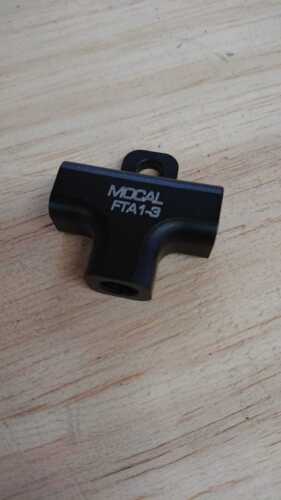
Slow progress on the quick rack build, I have lots of different size fire sleeve and colours, most of the hoses and fittings, I had made an order for the power steering hose ends from earls fitting a while back now but they have been on back order from America for ages, estimated that they would be in at the start of November!


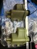
For those that havnt seen my other thread, this is what caused my rack to fail, the pinion bearing that sits into the rack had room to move, combined with m8 bolts used to bolt the pinion casing down with huge amounts of room spare, the only thing holding everything together was the tightness of the bolts. Comparing the tolerances to another rack I had spare, the quick rack had much more room to spare, I think if they would have built the rack up with a better casing, this might of not happened.


M8 bolts are used for this but it turns out M9 bolts from a bmw auto gearbox fit the pinion housing with a tad room to spare. The rack would need a bit drilled out though for them to work. Still undecided what I want to do, M10 bolts would guarantee a perfect fitment with zero room to spare, I mean its less than a 1mm extra drilled out so dont think it will be a problem.

IMG_0983.JPG


IMG_0982.JPG


If anyone has and other ideas about this please let me know, Im not a trained engineer so Im just going with my gut.

I made a video about this, first rack is the one that failed, second a spare rack, you can see the difference in size where the bearing sits.


IMG_0964.JPG
 
I was daunted by having to bleed the abs in such a small space and that the pump wasnt being registered, I decided to 'just' buy a tilton valve and make up what lines I needed, I also bought a sealey bleeder which can contain a couple litres of fluid and builds pressure with a hand pump not by tyre to make things as easy as possible.

I covered the lines in the engine bay with fire sleeve to act as abrasion resistance as well as heat, pointless? Maybe, I know the heat shield goes in between the lines and the exhaust but they are just so close. The brakes and power steering overheat on these cars, look where everything is.

IMG_1037.JPG

IMG_1041.JPG

IMG_1043.JPG

IMG_1046.JPG

IMG_1048.JPG

IMG_1050.JPG

IMG_1051.JPG


I had to run that o/s line funny because theres a minimum length needed after the bend to make the flare. Also my rivet tool didnt chop the ends off which Ill see to when everything else is finished.

You may notice the difference in brake line colours, the black rears have a slightly smaller I/D and the front greens standard 3/16 dimensions. This coupled with the larger 197 rear calipers (38mm bore) should help a bit with the bias as the rears wont lockup as quickly (before the need for the valve) As Im running the 274mm scenic setup. I hope that I have good modulation with this setup, and even with the bigger disc to run a race pad, but we will see!

hgfhgffhg.png


Link to original study.


Also Im oozing to clean up the engine bay and underside as it looks grim! When I have more space I will.
 
Nice, having also done this on other cars, the next time I do it I will place the adjuster valve somewhere that it can be adjusted while driving. Makes the initial setup so much easier!
Thanks. I forgot to say my reason behind the valve placement, basically It was too much work to go inside right now due to the lack of space, I was adamant on hardline which would of been interior out and a lot more work! Yeah I thought twice about it, would be nice to have adjustment on the fly!
 
An update on the rack. I decided to take the manual rack off the car to have a look as I wasnt happy with how it felt, I remember trying to adjust the pre load but it did not do much for the resistance of the rack, I could wind it out all the way and it was still kinda hard to turn. Upon inspection its filthy inside and even just turning the pinion out of the rack was tough. So I bought all new bearings and already have all the bushings to replace everything in the rack, apart from one tiny needle roller bearing which Im struggling to find.

IMG_1164.JPG


IMG_1162.JPG


IMG_1163.JPG


IMG_1174.JPG


I managed to get the inner bush out with a 19mm socket with some tape wrapped round the end for protection and an extension, a couple taps with a mallet to get it started and the rest just slides out.

IMG_1169.JPG


IMG_1182.JPG


IMG_1188.JPG


This is a spare rack I did the same too, Im going to be using this one as its much cleaner inside. It was given to me for free from another member (y) Really helped out with investigating the problem with the other rack as well.
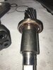
IMG_1193.JPG


Brand new koyo bearing, much better than the skf bearing of the same size. I also have a new ina bearing but theres actually a koyo already in the pinion which feels fine. I bought the ina one as that was what was in another rack.

IMG_1165.JPG
 

Attachments

  • IMG_1163.JPG
    IMG_1163.JPG
    1.2 MB · Views: 32
After some research I bought some EP 0 grease to assemble the rack with. With all new bearings and cleaned up this rack should feel great, I wont be getting any machining done on this one, I might use the M9 bolts though, I found an ARP m9 nut suitable but not sure if the bolt is long enough, will order and see. If not will just use 12.9 fasteners and do them up FT with loctite!

IMG_1191.JPG
 
Also brand new ATE pug 406 master cylinder on order! 23.8mm bore and 4 ports. Will put bleed nipples in 2 of them though instead of sacking off the t piece I already have, that way getting a bench bleed is guaranteed, even though Im sure pumping through using 1 man method is fine..
 
Ready to go back on the car. Its much smoother now, no notchiness or anything. Still quite a bit of resistance to turn, I dont really understand it, compared to the new oem rack I have which can be turned by hand with a bit of force, this takes quite a bit more.


IMG_1207.JPG


IMG_1209.JPG
 
After comparing and taking measurements of all three racks I have (new oem, manual quick rack and hydraulic) my original idea to re build the hydraulic quick rack is going ahead, Ive ordered everything I need inc new oem pas reservoir, various fittings from ebay and high pressure line fittings from america. I have a new vw polo rad and slim fan that arrived today to go on, its a bit smaller than original but not that much, I needed this to clear the lines from the pas pump.

It was interesting to have three types of rack to compare back to back, I built them up and measured how much force was required to turn while taking away as much slop in the gears as possible. This is what led to my decision to go ahead with the hydraulic rack.

IMG_1278.JPG


The return line from rack I just made. All three lines will have quick disconnects, if I need to check something theres zero mess taking the rack out this way.

IMG_1296.JPG


IMG_1307.JPG
 
Time for an update. Lots went well, one thing went wrong, it only takes one thing to put a halt on things though! And it was a really stupid rookie mistake! Although technically I could just swap out a part, Im going to leave it for now and come back to things after christmas, I may or may not go ahead with something I originally thought of a while back which Ill get into now.

First things first, I built the quick rack, the new casing has the right tolerance where the pinion bearing seats so everything went together perfect, if youve seen the video I posted at the start of the page, you'l see why I went to these lengths.

IMG_E1375.JPG


I built the 3 lines all with quick disconnects and having them has already made things a lot easier! Unfortunately the 120deg fitting pictured has a thin crack where the fitting seats, I really dont trust it especially being a high pressure hose. This made the quick disconnect position awkward as Id already cut the hose to length, defeating the original plan of everything being easily accessible, I ordered the fittings from the US and thinking I could I get the car mot'd before Christmas I just went ahead with things and used some fire sleeve as some protection for the qd.
Also these lines are a PITA to make! If anyone buys some have fun.

IMG_1367.JPG


Running a pick over the line its quite obvious that this is not up for the job.

IMG_1364.JPG


IMG_1376.JPG


I had a bit of a mission putting the rack and all the lines in, I left the subframe on and realised tightening the fittings on the rack wasnt possible, I removed the driveshaft and bracket but ended up having to drop the subframe. When I was dropping the subframe the column got 'caught' with the rack, once it was down I checked the rack and there was a slight bit of play, I couldnt believe this, I unbolted the rack and took everything apart and put a new pinion roller bearing in the casing after checking the main bearing which was perfectly fine, its still there... So I scratched my head, got the other rack I have and checked for play in that, less but still a slight amount. Granted it was the brt manual rack so different design. Im going to have a look at this properly to see what it is, I know that area of the rack is a weak point and I have a standard bearing that could replace the roller bearing with a slight bit of machining. Might seem like this is all pointless but the slight amount of play transmits through to the wheel and the whole point of what Im doing is to get rid of as much play as physically possible, without going to moog valves like on F1.

Once built up with the new bearing I still wanted to check the system before It gets bolted up and unreachable on the car.

IMG_1379.JPG


Everything was fine apart from this.. 😩 And it was my fault, where the copper washer sits, I had taken a very small amount of material off when filing the adapter for the HP hose. Such a stupid mistake but whatever, the guys I watch on youtube blow up engines weekly so dont think Im doing that bad 😄

IMG_1381.JPG


So heres the problem, if want to use that new part of the rack, I cant use banjo fittings and realistically need to re use the standard lines or make my own, not happening at this stage with how much Ive put in on relatively nothing. I could just use a spare rack part I have and get on with it, but I want the new part, who wouldnt?😄

So Im going to speak to the US company to hopefully send me another fitting so I could just use the standard lines and thus the lines just routed neater and more tucked away.
IMG_1390.JPG

IMG_1391.JPG


And while it was on the bench, the m9 fasteners arrived that I ordered at the start of November. So I guess it being off the car is not so bad, and Im in no rush now anyway... Well If I could have it working tomorrow I wouldnt complain.

IMG_1388.JPG


IMG_1389.JPG


You can just see the new air filter, the standard air box is huge and there wasnt enough space for the lines to route for easy access. So got some silicone tube and a ram air, nice and easy.
 
What I used for the pressure sensor. I dont like npt fittings but it worked fine.
IMG_1380.JPG


I had to drill and tap the thread for the m9 bolt and drill the hole for the other side.

IMG_1383.JPG
 
Im going to have a look at this properly to see what it is, I know that area of the rack is a weak point and I have a standard bearing that could replace the roller bearing with a slight bit of machining

Time for an update. Said machining has been done and the new bearing is in. My suspicions were correct, there is no binding no matter how much you tighten the pre load and the pinion is solid in the housing, before you could move it by hand. No idea why renault would design the racks like they did, if they were done properly like I have now done then I wouldnt of had a 600+quid rack fail in some thousand miles or so... The rack has been built with all new seals as well and I had bought a few different types of seal to pick which one had the best fitment, as the support rings in the seals are not made equal, I wanted it as tight as possible so the shaft could not move around in the rack.

So the full spec for the rack and steering is:

Machined pinion housing and new bearing (that actually does something)
Seals now better than oem (less play)
Cup racer bushes
Custom lines throughout and quick disconnects
New pas pump and reservoir
Twingo/epas solid lower steering joint

I was eager to test the car as Ive also done a brake overhaul, new 197 rear calipers, fully rebuilt front 197 calipers and new peugeot 406 mc. I havnt fit the 120deg fitting on the rack for the high pressure hose, Im going to buy more hose and make another line instead to swap them over in the future. Its a bit close to the heat shield and exhaust right now but it will be fine for the time being.


IMG_1677.JPG


I did the same as before, bolted the rack to the subframe off the car and checked for leaks, everything was good. Fluid was because I emptied what was left in the lines before bolting them up.

IMG_1678.JPG


Ive bought some self fusing silicone tape which is sometimes used on aeroplane hoses to seal the end of the fire sleeve. Ill put this on the new hose when I get to it.

IMG_1690.JPG


SiliconeWrapTape3.jpg


I only gave it a quick test up the road as furthest I can go right now, everything works.. Steering is sharp although brakes have been sat for a while, running ds1.11 up front and they need some heat to get going again. Cant make a proper judgement on the scenic rear conversion as havnt given them a proper go. All positive though, cant say anything bad apart from the awful rattles and cabin noise 😄
 
I want to add that after some thought, my original theory behind the rack failing, the first post of this page, may not have had any effect, Im now pretty sure its the upper bearing in the pinion which is now solved.


Top