
Ah ok cool. I thought about fitting a longacre pressure gauge some time ago but I’ve gone abs.Thanks.
Currently it just has a bleed nipple in there but my plan is to put a pressure sensor in there, thought I would get the fitting in whilst doing the pipe work.
ClioSport.net
-
When you purchase through links on our site, we may earn an affiliate commission. Read more here.
You are using an out of date browser. It may not display this or other websites correctly.
You should upgrade or use an alternative browser.
You should upgrade or use an alternative browser.
Fred and James’ Clio 182 Racecar Project
- Thread starter FrogJam Motorsport
- Start date
-
- Tags
- 182 race racecar track track build
Twingo 1??
ClioSport Club Member
Twingo 133 Cup,
Nice job on the lines! I have them to do on the Twingo next. Got lots of questions.
Where did you get the parts?
What tools made the job easier?
Does the clio not have a return fuel line?
Did you buy the connector that goes into the tank?
I am very nervous about doing it but it would cost a fortune to send it away to get done. Also wish I had a nice garage like that lol
Where did you get the parts?
What tools made the job easier?
Does the clio not have a return fuel line?
Did you buy the connector that goes into the tank?
I am very nervous about doing it but it would cost a fortune to send it away to get done. Also wish I had a nice garage like that lol
FrogJam Motorsport
ClioSport Trader
Nice job on the lines! I have them to do on the Twingo next. Got lots of questions.
Where did you get the parts?
What tools made the job easier?
Does the clio not have a return fuel line?
Did you buy the connector that goes into the tank?
I am very nervous about doing it but it would cost a fortune to send it away to get done. Also wish I had a nice garage like that lol
Thanks.
Got both fuel and brake lines from Atec (https://atec-autotechnik.com/), have A look at their catalogue, was great for working out what I needed. I still had a fair few questions but Kieron there was really patient with me and sorted me out as I had missed some bits I needed. And then they were great sorting the flexi fuel lines out so couldn’t recommend them enough.
These were the tools I used. Along with a sealey tools flare tool.
So for the aluminium hard lines larger bender, tube cutter, deburring tool.
Brake hard lines, small bender, tube cutter, deburring tool, and outer coating removal tool.
Fuel flexi lines just need a hacksaw, I used a bandsaw which worked well.
Brake flexi lines hacksaw and the mandrel tool which is specific for dash 3 sized line. This is used to separate the braided part of the line away from the inner tube, made them nice and easy to do.
The Clio does not have a return line as standard but I have already ran a second line for when we go to ITBs. Not quite sure the benefit of have a return line to be honest but it’s there if needed.
So the tank connector is usually a straight connector but as I cut the carbon canister out of the system I had a right angled connector from that. So I just reused a connector which was already on another part of the standard system. I could only find a replacement on eBay from China. Have a search for ‘7.89mm ID6 fuel fitting’ on eBay and you’ll find what you need.
The hardest part was bending the long runs in one length, brake lines are easy than the aluminium fuel line but even the aluminium hard lines have a little bit of give in them to get them lined up perfectly.
Give me a shout if you want to know any more.
FrogJam Motorsport
ClioSport Trader
The U piece of hose for bypassing the heater matrix, was that an off the shelf part or was it cut down from another piece? Need the same for mine
I just bought a single u bend piece and then cut down to length. The rest of the pipes are just a standard Clio set.
Pretty sure this is the actual one I bought but there are plenty of options.
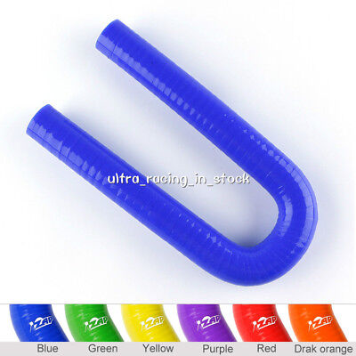
180 Degree Silicone Hose Elbow Bend 19mm 3/4 inch Coolant Radiator Pipe U Shape | eBay UK
The elbow coupler is UNIVERSAL, applicable to all kinds of vehicles. ● Silicone Hose Features Color: Blue.
www.ebay.co.uk
FrogJam Motorsport
ClioSport Trader
This is how it's done. Proper build. I'd love to do this one day when I get a unit or garage big enough.
Quite the escalation tho:
Buy track car - oh no gearbox bearing has gone - f**k it, full nut and bolt resto
Thanks.
Haha, it did just creep up on us. I would have liked to have driven it completely stock before doing the work but apart from that no regrets with the direction we have gone so far.
Touring_Rob
ClioSport Club Member
Part of the fun for me is building and working on these cars and I definitely wouldn't have the budget to pay someone else to build it anyway. That said, I'm still easily into £20k. For that money though I have a very competitive car that is always at the sharp end of 30-40 car grids.
Also worth mentioning that if you are starting from scratch, spending money on safety really can't be overstated. As witnessed by one of our race colleagues last weekend at Thruxton which he managed to walk away from.
f**k that! He did really well. Bet the marshals absolutely filled their orange pants. Glad he walked away.
Touring_Rob
ClioSport Club Member
f**k that! He did really well. Bet the marshals absolutely filled their orange pants. Glad he walked away.
I recon one of the biggest takeaways from that is to strap extinguishers down better, he's lucky it never took him out. Does anyone know if there was a mech failure which caused the crash? Early on he looked to have decent rear end grip but last couple of corners was sliding about a fair bit more, looks to early to be too much heat in the tyres? I honestly though he had caught it in time and kept his foot in like a champ.
robzracing
ClioSport Club Member
I spoke to him after. It was definitely cold tyres and trying too hard.
Nick Hamilton had an almost identical off a few years before in a Clio Cup. Right down to the fire extinguisher coming loose!
You can find it on YouTube
Sent from my iPhone using Tapatalk
Nick Hamilton had an almost identical off a few years before in a Clio Cup. Right down to the fire extinguisher coming loose!
You can find it on YouTube
Sent from my iPhone using Tapatalk
FrogJam Motorsport
ClioSport Trader
Post number 12.
Last thing left to do before turning it on was fluids, exhaust, air intake manifold and electrics.
Started work on the battery wiring. Gone with an Odyssey PC680 located behind the passenger seat and used a bulkhead post thing instead of just using a grommet, should do the job. Attached the main fuse to the side of the battery bracket.


Then it was time to get the looms out after putting them away 18 months ago.


Plugged everything in (well so I thought) and was ready to give it ago.

So engine turned over straight away but wasn’t firing. Decided to check if fuel pump was working and it had no power. So plugged my OBD reader in and it wasn't detecting any rpm, checked the crank sensor and we didn’t have one so then had to route around a number of boxes to find the old one. Luckily we still had it. So plugged that in and now getting power to the fuel pump.
Cranked the engine over for a good 30 seconds and still nothing. So disconnected the fuel line to the rail to see if there was fuel, there wasn’t. So with the fuel line into a bucket cranked the engine over for max 5 seconds and fuel started to come out. So fuel line back on and cranked the engine over again and it came to life.
Once running it was idling quite high and when you touched the throttle it wouldn’t reduce it’s speed, but looked at the intake manifold and it has 3 tube ports which weren‘t connected to anything so a bit of tape around these to block them off and the idle was back to normal.
So here is the customary startup video, no doubt many on here already but it was a great moment for us both and to say we were pleased was an understatement.
Next step was cutting out lots of wires and will explain the plan for that.
Last thing left to do before turning it on was fluids, exhaust, air intake manifold and electrics.
Started work on the battery wiring. Gone with an Odyssey PC680 located behind the passenger seat and used a bulkhead post thing instead of just using a grommet, should do the job. Attached the main fuse to the side of the battery bracket.
Then it was time to get the looms out after putting them away 18 months ago.
Plugged everything in (well so I thought) and was ready to give it ago.
So engine turned over straight away but wasn’t firing. Decided to check if fuel pump was working and it had no power. So plugged my OBD reader in and it wasn't detecting any rpm, checked the crank sensor and we didn’t have one so then had to route around a number of boxes to find the old one. Luckily we still had it. So plugged that in and now getting power to the fuel pump.
Cranked the engine over for a good 30 seconds and still nothing. So disconnected the fuel line to the rail to see if there was fuel, there wasn’t. So with the fuel line into a bucket cranked the engine over for max 5 seconds and fuel started to come out. So fuel line back on and cranked the engine over again and it came to life.
Once running it was idling quite high and when you touched the throttle it wouldn’t reduce it’s speed, but looked at the intake manifold and it has 3 tube ports which weren‘t connected to anything so a bit of tape around these to block them off and the idle was back to normal.
So here is the customary startup video, no doubt many on here already but it was a great moment for us both and to say we were pleased was an understatement.
Next step was cutting out lots of wires and will explain the plan for that.
FrogJam Motorsport
ClioSport Trader
Post number 13.
Since the car is now running I wanted to tackle the wiring.
The initial plan is to run the car with the standard ECU until we rebuild the engine with ITBs, cam etc then will go to a stand-alone ecu, but no idea when we will do that, could be a while off. So we have decided step one would be to strip the original loom down as much as possible and include a digital dash and power distribution module. So the PDM will control as much as possible but still need to work out exactly how the PDM will fit in with the existing ecu/loom, hence whilst stripping the original loom I plan to work out the best way to combine the old and new systems.
Going to go with the ECU Master gear so going to order an ADU7, PMU, gps, battery isolator and CAN keyboard shortly.
I thought it was a good idea to not touch the original looms at all until firing the car up. There was a lot of wires/connectors not connected so first step was to remove all of this and trace the wires back.


Started with the rear loom (from passenger side connector), all bar the fuel tank connector was to go from this one as the PMU is going to control all lights etc, so will save the connectors to the brake lights to reuse in the new loom. So the rear loom started as this:

And ended up with this, 2 wires for fuel level sensor, 1 for fuel pump power and a ground. I will change the large OEM loom connector to one of the DT series connectors. So DTM for 7amps, DT for 13amps max and DTP for 25amps max which happens to fit in with the PMU max channel outputs.

So connected the loom back into the car and just double checked it still started. But this one didn’t have anything important apart from the fuel pump so wasn't expecting anything to go wrong.
Then started the same process on the dash loom. With this one, kept the 2 dash connectors, throttle, brake, clutch, immobiliser, key, 3 uch connectors, obd port. This was the loom pretty much at the start of the process.

Halfway through:

And then pretty much done for the time being:


Since the car is now running I wanted to tackle the wiring.
The initial plan is to run the car with the standard ECU until we rebuild the engine with ITBs, cam etc then will go to a stand-alone ecu, but no idea when we will do that, could be a while off. So we have decided step one would be to strip the original loom down as much as possible and include a digital dash and power distribution module. So the PDM will control as much as possible but still need to work out exactly how the PDM will fit in with the existing ecu/loom, hence whilst stripping the original loom I plan to work out the best way to combine the old and new systems.
Going to go with the ECU Master gear so going to order an ADU7, PMU, gps, battery isolator and CAN keyboard shortly.
I thought it was a good idea to not touch the original looms at all until firing the car up. There was a lot of wires/connectors not connected so first step was to remove all of this and trace the wires back.
Started with the rear loom (from passenger side connector), all bar the fuel tank connector was to go from this one as the PMU is going to control all lights etc, so will save the connectors to the brake lights to reuse in the new loom. So the rear loom started as this:
And ended up with this, 2 wires for fuel level sensor, 1 for fuel pump power and a ground. I will change the large OEM loom connector to one of the DT series connectors. So DTM for 7amps, DT for 13amps max and DTP for 25amps max which happens to fit in with the PMU max channel outputs.
So connected the loom back into the car and just double checked it still started. But this one didn’t have anything important apart from the fuel pump so wasn't expecting anything to go wrong.
Then started the same process on the dash loom. With this one, kept the 2 dash connectors, throttle, brake, clutch, immobiliser, key, 3 uch connectors, obd port. This was the loom pretty much at the start of the process.
Halfway through:
And then pretty much done for the time being:
FrogJam Motorsport
ClioSport Trader
Post number 13 continued.
Next was the same to the engine loom.
So connectors to keep here were:

Halfway through:

And then with the engine loom back in the car:

So after the first step of stripping wires from the looms this was the amount of wires I had cut out.

The car is back up and running now so the next step is to go into more detail with the loom and remove more wires which are redundant. But happy with how the first step with the loom had gone.
Next was the same to the engine loom.
So connectors to keep here were:
- MAP
- dephaser solenoid / vvt
- alternator (not sure what this one actually does)
- oil pressure
- oil level
- knock
- intake air
- coolant temp
- crank sensor
- coil pack
- Large ecu connector
- starter motor
- Lambra sensor 1 and 2
- reverse sensor
- relays
- fuses
Halfway through:
And then with the engine loom back in the car:
So after the first step of stripping wires from the looms this was the amount of wires I had cut out.
The car is back up and running now so the next step is to go into more detail with the loom and remove more wires which are redundant. But happy with how the first step with the loom had gone.
Last edited:
FrogJam Motorsport
ClioSport Trader
Post number 14.
Really need to do these more often. Done a fair amount since the last post.
Not sure if I mentioned it but found a small oil leak which looked like it was coming from the end of the gearbox. So before going any further thought I would sort it. Assumed it was to do with the 5th gear end cap, one of the threaded holes was a bit knackered so decided to buy a new seal and helicoil the threaded hole. New seal and a helicoil later and no more leak. Should have said I took the engine out to do this, was probably possible to do without taking it out but thought I may as well so could have a proper look. From having it in a running state it took 1.5 hours for me to get it out, was pretty happy with that, sure it will be quicker next time. Gave the end cap and good clean and paint too.

Spent a day getting the doors, bonnet, boot, bumpers out from where I had stored them for the last 18 months and fitting them, so back end is together now and test fitted the front but took them back off so I don’t mess anything up whilst sorting the wiring out. All went back together rather well.


Wanted to get rid of some more wires so had a read through the workshop manual and pulled as many fuses and relays as I could but enough to allow the car to run.


So now the fun part, the ECU Master gear arrived, I was like a kid at Christmas.
ECU Master ADU7, PMU, Battery Isolator, CAN Keyboard, GPS to CAN and USB to CAN.
Bought the stuff from RRR Engineering who were very helpful. Plan is to go to the stand alone EMU Black later down the line once we want to do engine modifications.

First job was to make a dash mount/cowl and decide where to mount it.
We decided to mount the dash in the centre of the car on the dash bar, many people on Instagram questioned the position but we’re happy with it. Viewing the dash through the wheel didn’t really work due to our height difference, probably didn’t help that we went for the larger dash though, but we also preferred the dash to be more in our eye line. Then mounting the dash above the wheel was just about doable for myself but restricted the view of the dash slightly for James. Hence we went for the middle of the dash bar which worked great for both of us.
Fabricated the dash mount from sheet aluminium, did some drawings on CAD to make sure it was all even and came out rather well for my first time welding aluminium. Certainly need more practice with TIG. Then finished it off with matte black spray paint.


Really need to do these more often. Done a fair amount since the last post.
Not sure if I mentioned it but found a small oil leak which looked like it was coming from the end of the gearbox. So before going any further thought I would sort it. Assumed it was to do with the 5th gear end cap, one of the threaded holes was a bit knackered so decided to buy a new seal and helicoil the threaded hole. New seal and a helicoil later and no more leak. Should have said I took the engine out to do this, was probably possible to do without taking it out but thought I may as well so could have a proper look. From having it in a running state it took 1.5 hours for me to get it out, was pretty happy with that, sure it will be quicker next time. Gave the end cap and good clean and paint too.
Spent a day getting the doors, bonnet, boot, bumpers out from where I had stored them for the last 18 months and fitting them, so back end is together now and test fitted the front but took them back off so I don’t mess anything up whilst sorting the wiring out. All went back together rather well.
Wanted to get rid of some more wires so had a read through the workshop manual and pulled as many fuses and relays as I could but enough to allow the car to run.
So now the fun part, the ECU Master gear arrived, I was like a kid at Christmas.
ECU Master ADU7, PMU, Battery Isolator, CAN Keyboard, GPS to CAN and USB to CAN.
Bought the stuff from RRR Engineering who were very helpful. Plan is to go to the stand alone EMU Black later down the line once we want to do engine modifications.
First job was to make a dash mount/cowl and decide where to mount it.
We decided to mount the dash in the centre of the car on the dash bar, many people on Instagram questioned the position but we’re happy with it. Viewing the dash through the wheel didn’t really work due to our height difference, probably didn’t help that we went for the larger dash though, but we also preferred the dash to be more in our eye line. Then mounting the dash above the wheel was just about doable for myself but restricted the view of the dash slightly for James. Hence we went for the middle of the dash bar which worked great for both of us.
Fabricated the dash mount from sheet aluminium, did some drawings on CAD to make sure it was all even and came out rather well for my first time welding aluminium. Certainly need more practice with TIG. Then finished it off with matte black spray paint.
FrogJam Motorsport
ClioSport Trader
Post number 15.
Continued mounting the ECU Master kit. Had started to make the keypad frame a while back, wanted to keep it bolt on so it was easy to make a new one if it needed to move or alter the design at some point. So was a bit rough and ready but turned out ok, I’ll try making one out of aluminium once I get better at tig welding. Finished off with some matte black paint. As well as the CAN keyboard the fire extinguisher control unit and battery isolator reset button was to be mounted to the frame.


Needed some where to mount the battery isolator and wanted somewhere to mount the Stilo Verbacom unit, phone and usb chargers so made a mounting plate in the centre behind the handbrake. Got a radlok connector coming for the battery ground to that’s quick and easy to remove if required.


Used the same idea for the PMU and GPS mounting. Thought this would be best on the front bulkhead. Keeps it out the way in case a passenger comes along.

Made the initial loom to connect the ECU Master kit to get in up and running. Connected all items on the same CAN bus, had to change the keypad CAN bus speed but was nice and easy using the ecu master software. Still worked by connecting them all up even with different speeds then just changing the computer interface to 500 kbit/s to change the keypad to 1 mbit/s, so couldn‘t be more simple.


Once the PMU, ADU, battery isolator, GPS and CAN keyboard were talking to each other I set about getting rid of the key and ignition barrel using the PMU to turn the ignition on and start the car. Since stripping lots of the wires out the ignition 1 circuit didn’t do anything so just needed power for ignition 2 and starter which were powered directly from the PMU. If anyone is interested in how the PMU and ADU are programmed I could do a post about that, however both the manuals get you most of the way there. The procedure is pretty simple, firstly the battery isolator needs turning on, then turn ignition 2 on, then hold for the starter. So here is a video of the car firing up using the CAN keyboard.
Continued mounting the ECU Master kit. Had started to make the keypad frame a while back, wanted to keep it bolt on so it was easy to make a new one if it needed to move or alter the design at some point. So was a bit rough and ready but turned out ok, I’ll try making one out of aluminium once I get better at tig welding. Finished off with some matte black paint. As well as the CAN keyboard the fire extinguisher control unit and battery isolator reset button was to be mounted to the frame.
Needed some where to mount the battery isolator and wanted somewhere to mount the Stilo Verbacom unit, phone and usb chargers so made a mounting plate in the centre behind the handbrake. Got a radlok connector coming for the battery ground to that’s quick and easy to remove if required.
Used the same idea for the PMU and GPS mounting. Thought this would be best on the front bulkhead. Keeps it out the way in case a passenger comes along.
Made the initial loom to connect the ECU Master kit to get in up and running. Connected all items on the same CAN bus, had to change the keypad CAN bus speed but was nice and easy using the ecu master software. Still worked by connecting them all up even with different speeds then just changing the computer interface to 500 kbit/s to change the keypad to 1 mbit/s, so couldn‘t be more simple.
Once the PMU, ADU, battery isolator, GPS and CAN keyboard were talking to each other I set about getting rid of the key and ignition barrel using the PMU to turn the ignition on and start the car. Since stripping lots of the wires out the ignition 1 circuit didn’t do anything so just needed power for ignition 2 and starter which were powered directly from the PMU. If anyone is interested in how the PMU and ADU are programmed I could do a post about that, however both the manuals get you most of the way there. The procedure is pretty simple, firstly the battery isolator needs turning on, then turn ignition 2 on, then hold for the starter. So here is a video of the car firing up using the CAN keyboard.
FrogJam Motorsport
ClioSport Trader
Post number 15 continued.
Started the rear loom for the tail lights. Plan was to combine brake and rear lights to have dual brake lights, and both indicator and reverse lights together so can have dual indicators. Can always take a bulb out if it’s pointless. Having an LED rain light too. Used the existing taillight connectors and wires and connected these to a deutsch DT series connector to continue the loom onto the PMU. Makes it easy to test the lights by turning all the output on on the laptop prior to assigning the switches or controls.


I did wire in the spoiler light into the same circuit as the brake lights but doesn’t seem to be working so will need to have a look at whats causing that. It’s getting power so assuming the spoiler light is just broken.
We then deviated from the original plan and decided to bite the bullet and go to a stand alone ECU. It was always the idea that we would go to a stand-alone later down the line but rather than messing around sorting all the wiring out now to work with the standard ECU and UCH and then changing later we may as well get it done now. And will be tasty to have features like a pit limiter, traction control for wet starts etc.


Along with the wide band oxygen sensor, decided to get a new coil pack and a range of sensors. Main ones being engine oil temp and pressure sensors. Hoping to use the existing coolant temperature sensor, but would be even better if I could replace it with a new one but haven’t looked what thread size the coolant sensor is yet.
Moved the coil pack to the side of the engine in preparation for ITBs and potentially a different manifold, no decision have been made yet though. Made a custom bracket which bolted to the same location as the engine hoist bracket.


Since the direction is now with the stand-alone ecu (the blue rope maybe a give away) I have started work on a new engine loom.
So the next post will be all about the new engine loom.
Started the rear loom for the tail lights. Plan was to combine brake and rear lights to have dual brake lights, and both indicator and reverse lights together so can have dual indicators. Can always take a bulb out if it’s pointless. Having an LED rain light too. Used the existing taillight connectors and wires and connected these to a deutsch DT series connector to continue the loom onto the PMU. Makes it easy to test the lights by turning all the output on on the laptop prior to assigning the switches or controls.
I did wire in the spoiler light into the same circuit as the brake lights but doesn’t seem to be working so will need to have a look at whats causing that. It’s getting power so assuming the spoiler light is just broken.
We then deviated from the original plan and decided to bite the bullet and go to a stand alone ECU. It was always the idea that we would go to a stand-alone later down the line but rather than messing around sorting all the wiring out now to work with the standard ECU and UCH and then changing later we may as well get it done now. And will be tasty to have features like a pit limiter, traction control for wet starts etc.
Along with the wide band oxygen sensor, decided to get a new coil pack and a range of sensors. Main ones being engine oil temp and pressure sensors. Hoping to use the existing coolant temperature sensor, but would be even better if I could replace it with a new one but haven’t looked what thread size the coolant sensor is yet.
Moved the coil pack to the side of the engine in preparation for ITBs and potentially a different manifold, no decision have been made yet though. Made a custom bracket which bolted to the same location as the engine hoist bracket.
Since the direction is now with the stand-alone ecu (the blue rope maybe a give away) I have started work on a new engine loom.
So the next post will be all about the new engine loom.
FrogJam Motorsport
ClioSport Trader
Really happy with the dash position, feels really natural. Obviously may be different once actually driving but pretty sure it’ll be all good.
FrogJam Motorsport
ClioSport Trader
Post number 16.
It was that time to make a start of the engine wiring loom. Spent many evenings planning the loom out with a spreadsheet, plan was to have two Deutsch HDP20s as bulkhead connectors, the other side of which will be right next to the PMU/EMU Black.
Here is a list of every connector I had planned for the engine loom:
First step was to plan the routing and then make a template, used a couple sizes of rope to make it and lots of cable ties.

This template was then transferred onto a board with each branch/junction marked with a cable tie mount.


Then could start running wires marking them off one by one of the spreadsheet and putting a cable marker at the bulkhead end to make it easier for when I come to pin the bulkhead connectors. Once I had placed all the wires I started to remove the cable ties and replace them with kapton tape.

For sleeving I used adhesive lined heat shrink from hilltop products and raychem SCL (rigid heat shrink) for all joints and branches. I added a cable tie at each branch to add some additional support.


Once all the sleeving was complete I fitted the loom into the car which then meant I could complete all the connector ends. Found it just as easy to complete these with the loom in the car as then all the lengths could be bang on. So same as running the wires I worked my way through the spreadsheet marking each connector off as I went. I will do another post with each of the new standard OEM electrical connectors I found.


That just left the 2 bulkhead connectors to do.
It was that time to make a start of the engine wiring loom. Spent many evenings planning the loom out with a spreadsheet, plan was to have two Deutsch HDP20s as bulkhead connectors, the other side of which will be right next to the PMU/EMU Black.
Here is a list of every connector I had planned for the engine loom:
- Coolant Fans
- Headlight Left and Right
- Windscreen Wiper
- Injector 1, 2, 3 and 4
- Coils
- Starter Motor
- Throttle Body
- Dephaser Solenoid
- Crank Sensor
- Coolant Temperature
- Intake Air Temperature
- MAP Sensor
- Engine Oil Temperature
- Engine Oil Pressure
- Oil Level Sensor
- Knock Sensor
- Fuel Pressure Sensor
- Alternator Signal
- Gearbox Oil Temperature
- Brake Pressure
- Wide Band O2 Sensor
- Brake Fluid Level
- Wheel Speed Left and Right
- Fire Extinguisher Button
- Battery Isolator Kill Button
First step was to plan the routing and then make a template, used a couple sizes of rope to make it and lots of cable ties.
This template was then transferred onto a board with each branch/junction marked with a cable tie mount.
Then could start running wires marking them off one by one of the spreadsheet and putting a cable marker at the bulkhead end to make it easier for when I come to pin the bulkhead connectors. Once I had placed all the wires I started to remove the cable ties and replace them with kapton tape.
For sleeving I used adhesive lined heat shrink from hilltop products and raychem SCL (rigid heat shrink) for all joints and branches. I added a cable tie at each branch to add some additional support.
Once all the sleeving was complete I fitted the loom into the car which then meant I could complete all the connector ends. Found it just as easy to complete these with the loom in the car as then all the lengths could be bang on. So same as running the wires I worked my way through the spreadsheet marking each connector off as I went. I will do another post with each of the new standard OEM electrical connectors I found.
That just left the 2 bulkhead connectors to do.
FrogJam Motorsport
ClioSport Trader
Post number 16 continued.
The Deutsch HDP20 connectors are great, very easy to crimp and pin so would highly recommend and are a fraction of the price of Autosport connectors.

I did have some boots for the bulkhead connectors but I had not left anywhere near enough room between the connector and branch to allow the boot to be slid past the end of the wires to pin the connector first so that one thing I would do different next time but the connectors are meant to be water proof without the boots so should be fine.
Then had the other side of the bulkhead connectors to do which only had a short length of wire to the PMU and EMU Black.


Then I went through connecting and testing each component one by one. And amazingly enough everything seems to be working as it should.

Next post will be starting to sort a map out to get the car started for the first time with the stand-alone ECU.
The Deutsch HDP20 connectors are great, very easy to crimp and pin so would highly recommend and are a fraction of the price of Autosport connectors.
I did have some boots for the bulkhead connectors but I had not left anywhere near enough room between the connector and branch to allow the boot to be slid past the end of the wires to pin the connector first so that one thing I would do different next time but the connectors are meant to be water proof without the boots so should be fine.
Then had the other side of the bulkhead connectors to do which only had a short length of wire to the PMU and EMU Black.
Then I went through connecting and testing each component one by one. And amazingly enough everything seems to be working as it should.
Next post will be starting to sort a map out to get the car started for the first time with the stand-alone ECU.
haimsey
ClioSport Club Member
ph2 172
Brilliant work with this build, really do enjoy threads like this! I'd love the space and time (new dad) to crack on. Can't wait to see the next lot of updates ")
I'd be interested to see the drawings for the cage, always fancied designing my own cage to have made up
I'd be interested to see the drawings for the cage, always fancied designing my own cage to have made up
FrogJam Motorsport
ClioSport Trader
Brilliant work with this build, really do enjoy threads like this! I'd love the space and time (new dad) to crack on. Can't wait to see the next lot of updates
I'd be interested to see the drawings for the cage, always fancied designing my own cage to have made up
Thanks, appreciate it. Glad you are enjoying it!
Here are the 3 bent tube drawings I sent to tubebender tom. I had the tubes made to be a little longer than needed so I could get them myself to the specific length with the notches.
To get to that point I went through a few steps. I mocked up the roll cage using pipe insulation to work out where abouts i would want the bends. Then using a 3 plane laser I could measure the coordinates of each of these bends/junctions.
From these measurements I then created a CAD model on the full cage.
As well as the cage measurements I took a number of coordinates of the body shell and made a bit of a point cloud with about 20-30 points to make sure the CAD model cleared the body shell coordinates.
From the CAD model I printed out a 1:1 scale drawing and cut out an MDF template of the main hoop and side tubes.
All seemed to be working out so took the plunge and got the tube bent.
I was worried that the cage was going to be a problem with clearance to my helmet as I’m quite tall and we were going to move the seat so far back. So the main hoop is quite a bit further back than other cages I’ve seen. But really pleased with how it’s turned out especially for my first go. Think when I do another one I would get the front tube above the windscreen bent to follow the roof a little better and would look into using different size tubes for certain parts but apart from that not much I would change. Not sure how other people work out the cage but the way I did it seemed to work a treat.
Just let me know if you have any other questions when you get there.
Nafoff
ClioSport Club Member
Brilliant work with this build, really do enjoy threads like this! I'd love the space and time (new dad) to crack on. Can't wait to see the next lot of updates
I'd be interested to see the drawings for the cage, always fancied designing my own cage to have made up
It is crazy how much time little ones take up isn't it. I have struggled to do the smallest jobs on mine since I have been a dad
Mr Underhill
ClioSport Club Member
Wait until you become a grandad. You just get rid of one lot and they come back with reinforcements.It is crazy how much time little ones take up isn't it. I have struggled to do the smallest jobs on mine since I have been a dad
haimsey
ClioSport Club Member
ph2 172
Thanks for posting the cage related stuff, the laser level looks to have made things a lot easier. Always a nice feeling knowing you've designed something yourself once the jobs done.
It is indeed, I've been swapping my dog one mount for a fortnight. He just always wants my ramps for jumping his balance bike off!It is crazy how much time little ones take up isn't it. I have struggled to do the smallest jobs on mine since I have been a dad
FrogJam Motorsport
ClioSport Trader
dont be afraid to alter the exhaust tunnel and floor to get the seat low. I had to do this to my 205. We also put the cage main hoop back 6-7inches behind the normal position.
Thanks.
Think I’ll have to look into a slider for the seat too as two of us are sharing the car. But not sure what is ok for regs yet. So may need to lower the seat mounts to negate the slider height but something to sort out once the car is up and running.
This is an amazing thread! I have just secured a space to refurb my track 172 Cup.
I guess what I will be doing is a poor mans version of this thread.. lmao!
Great work OP!! Where are you at with it now?
Mind me asking how much all the ECU Master stuff (phase 1 order, not including the stand alone ECU stuff).
I guess what I will be doing is a poor mans version of this thread.. lmao!
Great work OP!! Where are you at with it now?
Mind me asking how much all the ECU Master stuff (phase 1 order, not including the stand alone ECU stuff).
FrogJam Motorsport
ClioSport Trader
Thanks, appreciate it!This is an amazing thread! I have just secured a space to refurb my track 172 Cup.
I guess what I will be doing is a poor mans version of this thread.. lmao!
Great work OP!! Where are you at with it now?
Mind me asking how much all the ECU Master stuff (phase 1 order, not including the stand alone ECU stuff).
Its getting very close to being done. I am now waiting for the plastic windows to arrive. Meant to be here in a week or two (ordered them in October), once they are here we can glue the rear side windows and windscreen in. Then it’s pretty much ready for mapping. I’ll get an update sorted on here. Find the updates harder to do when its been lots of smaller jobs. This weekend i’ve been sorting a set of Laguna uprights out, slight change of plan but will explain in the following updates. I am up to date on Instagram if you are interested (clio_182).
The first lot of ecu master gear was 3k. That included ADU7, PMU, battery isolator, GPS, USB to CAN and 12 key keypad.
FrogJam Motorsport
ClioSport Trader
Post Number 17.
Sorry been a while since the last post. Lots of smaller stuff been done over the last couple of months however.
Following on from the last post I was at the stage of getting the engine started up with the stand alone ECU Master EMU Black. On the whole setup of the initial map was pretty straight forward. Had most of the settings from data sheets and stole some information from the ME442 basemap available online such as the timing trigger. If any one needs any help or information then give me a shout, I had a lot of head scratching moments so will be happy to try and help.

Spent a fair bit of time on the laptop getting everything working before turning on for the first time. All was going well but the throttle body didn’t seem right. Kept fully opening once the ecu was powered. I got round this by inverting the throttle mapping, however this then meant the idle control couldn’t sort itself out as can be heard in the below video. had to keep blipping the throttle to keep it running as the idle control wasn’t working. I also checked timing with a timing gun before firing up. But was really pleased it ran even though it wouldn’t idle.
That evening I sent RRR Engineering an email at 9 o’clock, was really impressed because Greg got back to me within 10 minutes and said sounds like I had the +/- signal the wrong way round so give that ago. Sure enough he was right. So could put the throttle map back to normal and sure enough it was happily idle.
There is a few things I still want to sort out like how to get the starter button act as the stop button too but I’m sure RRR Engineering will be able to sort that in no time when it goes down there to be mapped. So till then that was the electrics pretty much sorted. Internal wiring needed a tidy up at some point.
Sorry been a while since the last post. Lots of smaller stuff been done over the last couple of months however.
Following on from the last post I was at the stage of getting the engine started up with the stand alone ECU Master EMU Black. On the whole setup of the initial map was pretty straight forward. Had most of the settings from data sheets and stole some information from the ME442 basemap available online such as the timing trigger. If any one needs any help or information then give me a shout, I had a lot of head scratching moments so will be happy to try and help.
Spent a fair bit of time on the laptop getting everything working before turning on for the first time. All was going well but the throttle body didn’t seem right. Kept fully opening once the ecu was powered. I got round this by inverting the throttle mapping, however this then meant the idle control couldn’t sort itself out as can be heard in the below video. had to keep blipping the throttle to keep it running as the idle control wasn’t working. I also checked timing with a timing gun before firing up. But was really pleased it ran even though it wouldn’t idle.
That evening I sent RRR Engineering an email at 9 o’clock, was really impressed because Greg got back to me within 10 minutes and said sounds like I had the +/- signal the wrong way round so give that ago. Sure enough he was right. So could put the throttle map back to normal and sure enough it was happily idle.
There is a few things I still want to sort out like how to get the starter button act as the stop button too but I’m sure RRR Engineering will be able to sort that in no time when it goes down there to be mapped. So till then that was the electrics pretty much sorted. Internal wiring needed a tidy up at some point.
FrogJam Motorsport
ClioSport Trader
Post Number 18.
Now for lots of smaller jobs I got done over Christmas.
We had some debate and research on what the best form of ventilation was, we settled with a roof scoop to begin with and see how we get on.
Went with the CM Composites one as it had a low profile design inside and out. Used the q max cutters to cut a number of holes to let the air through and bolt it all together. Had to move the drain plug to clear the roll cage too. Time will tell if it does the job or not.


Next on the list was the doors and body work. Plan was to keep the doors stock for the time being until we decide what to do but add a set of trackcar door cards, these were actually bought over 2 years ago before the gearbox went bang and things escalated so was nice to open them at last. Aero catches for the bonnet and Pitking quick release pins for the bumper.


Now for lots of smaller jobs I got done over Christmas.
We had some debate and research on what the best form of ventilation was, we settled with a roof scoop to begin with and see how we get on.
Went with the CM Composites one as it had a low profile design inside and out. Used the q max cutters to cut a number of holes to let the air through and bolt it all together. Had to move the drain plug to clear the roll cage too. Time will tell if it does the job or not.
Next on the list was the doors and body work. Plan was to keep the doors stock for the time being until we decide what to do but add a set of trackcar door cards, these were actually bought over 2 years ago before the gearbox went bang and things escalated so was nice to open them at last. Aero catches for the bonnet and Pitking quick release pins for the bumper.
FrogJam Motorsport
ClioSport Trader
Post Number 18 continued.
The pitking pins worked great. Seen a fair few people use them on here so nothing new.
The original bumper attachment/catch mechanism was really stiff to remove so I smoothed the catches out to allow the side to come up easier but still provide some positive location.

So on to Christmas Day and James had bought be a pair of race gloves so had to try them on whilst sitting in the car, thought it would be rude not to! Got me rather excited for getting the car sorted, starting to feel like it’s really not far away either.

Rain light fitted to the boot. Didn’t want to drill a hole in a prominent place so did it behind the numberplate so boot is still suitable for someone’s road car. Assuming we will go for a fibreglass boot at some point but certainly a decision for a later date. Rain light fitted nicely underneath the boot release but still enough room to open it.

Small detail but added a dual USB charger port inside for cameras, phone, radio system etc. Can always add another one if two isn’t enough. On the last couple of track days in James’ car it was a pain keeping the cameras charged So will be great to be able to keep the plugged in.

External battery isolator and fire extinguisher buttons connected up. Need to add the stickers at some point.

I was in the mood for a bit of easy fabrication so decided to make a string alignment jig which would easily attach to the car. So a few measurements for the rear bumper and knocked an Idea up.


The pitking pins worked great. Seen a fair few people use them on here so nothing new.
The original bumper attachment/catch mechanism was really stiff to remove so I smoothed the catches out to allow the side to come up easier but still provide some positive location.
So on to Christmas Day and James had bought be a pair of race gloves so had to try them on whilst sitting in the car, thought it would be rude not to! Got me rather excited for getting the car sorted, starting to feel like it’s really not far away either.
Rain light fitted to the boot. Didn’t want to drill a hole in a prominent place so did it behind the numberplate so boot is still suitable for someone’s road car. Assuming we will go for a fibreglass boot at some point but certainly a decision for a later date. Rain light fitted nicely underneath the boot release but still enough room to open it.
Small detail but added a dual USB charger port inside for cameras, phone, radio system etc. Can always add another one if two isn’t enough. On the last couple of track days in James’ car it was a pain keeping the cameras charged So will be great to be able to keep the plugged in.
External battery isolator and fire extinguisher buttons connected up. Need to add the stickers at some point.
I was in the mood for a bit of easy fabrication so decided to make a string alignment jig which would easily attach to the car. So a few measurements for the rear bumper and knocked an Idea up.
FrogJam Motorsport
ClioSport Trader
Post Number 18 continued.
Since the wiring seemed like it was all working ok it was time to give the wiring a tidy up inside. Used braided sleeve for a lot of the wiring on the bulkhead so it would be nice and easy to add or modify any of the wiring at a later date.


The wiring on the bulkhead isn’t as tidy as I would have liked it to be but functional is better than it just looking tidy I suppose. Hopefully it won’t be noticed once driving. Seems to be hidden a bit more from the drivers eye.

Added the cage padding and checked on head room with my helmet on. Very close but just about manageable. Can gain 5mm with different seat bars, MSA/FIA says 35mm seat rails are ok but I ended up using 40mm so that could gain some room. Can move the seat down one notch on the side mounts too. The plan is for me to remove the seat cushion to drive and James can add the cushion in which will give us the different driving positions we need. May look at a resin seat bag instead of just the cushion difference if needed.

Air intake was next. Thought of the different options for this but kept coming back to the same design as what Scott has done on his car (tomtek / pro-am racing) so I am afraid this is just a copy of what they have done. Revotec intake duct, ASH hoses and a carbon filter air box. Gives the best combination of ram air feed and cold air feed. Added stainless hose clamps and seems solid even without a mount for the carbon air box.


I gave the inside a good clean when tidying the wiring up, so finally decided to buy a car cover, Halfords outdoor car cover for £40. Extra small and fits the Clio perfectly.

Since the wiring seemed like it was all working ok it was time to give the wiring a tidy up inside. Used braided sleeve for a lot of the wiring on the bulkhead so it would be nice and easy to add or modify any of the wiring at a later date.
The wiring on the bulkhead isn’t as tidy as I would have liked it to be but functional is better than it just looking tidy I suppose. Hopefully it won’t be noticed once driving. Seems to be hidden a bit more from the drivers eye.
Added the cage padding and checked on head room with my helmet on. Very close but just about manageable. Can gain 5mm with different seat bars, MSA/FIA says 35mm seat rails are ok but I ended up using 40mm so that could gain some room. Can move the seat down one notch on the side mounts too. The plan is for me to remove the seat cushion to drive and James can add the cushion in which will give us the different driving positions we need. May look at a resin seat bag instead of just the cushion difference if needed.
Air intake was next. Thought of the different options for this but kept coming back to the same design as what Scott has done on his car (tomtek / pro-am racing) so I am afraid this is just a copy of what they have done. Revotec intake duct, ASH hoses and a carbon filter air box. Gives the best combination of ram air feed and cold air feed. Added stainless hose clamps and seems solid even without a mount for the carbon air box.
I gave the inside a good clean when tidying the wiring up, so finally decided to buy a car cover, Halfords outdoor car cover for £40. Extra small and fits the Clio perfectly.
I've just spent the last half hour reading through the whole build. The attention to detail is so so good. You sir have some serious talent. Couple of questions from myself though.
The clamps you used around the blue silicone hoses? Whats the name of these? And if you have the sizes you used for the full kit would be mega. I only ask as ive recently bought the same silicone hose kit but been told to avoid the generic jubilee clamps.
Also, the rear rain light, have you connected this to work as a brake light? Or is this on its own circuit connected to a switch so you can choose when to turn it on or off?
loggyboy
ClioSport Club Member
Clamps look like Mikalor to me.I've just spent the last half hour reading through the whole build. The attention to detail is so so good. You sir have some serious talent. Couple of questions from myself though.
The clamps you used around the blue silicone hoses? Whats the name of these? And if you have the sizes you used for the full kit would be mega. I only ask as ive recently bought the same silicone hose kit but been told to avoid the generic jubilee clamps.
Also, the rear rain light, have you connected this to work as a brake light? Or is this on its own circuit connected to a switch so you can choose when to turn it on or off?
Brilliant build thread, looking forward to seeing more.
FrogJam Motorsport
ClioSport Trader
Thanks.I've just spent the last half hour reading through the whole build. The attention to detail is so so good. You sir have some serious talent. Couple of questions from myself though.
The clamps you used around the blue silicone hoses? Whats the name of these? And if you have the sizes you used for the full kit would be mega. I only ask as ive recently bought the same silicone hose kit but been told to avoid the generic jubilee clamps.
Also, the rear rain light, have you connected this to work as a brake light? Or is this on its own circuit connected to a switch so you can choose when to turn it on or off?
Loggyboy is correct, they are Mikalor clamps. However, people have said not to use them and to use the normal jubilee clamps so I have both. I have no experience with either so cannot comment on them. The Mikalor ones seem much nicer and don’t cut the hose at all but if they come loose then it doesn’t matter What they look like. I think it’s probably the same with all these things though, left unchecked for a while one could come loose and cause a leak so make sure they are tight each track day and I am sure they will be fine. I will measure them later. Can’t find the list of the exact sizes.
I am using the ECU Master PMU (a power distribution module) so the rain light is connect to its own circuit and then I can program it to do what ever I want. So for the time being it’s programmed to Come on with the brake lights. However, for the MSA regs it’s not allowed to be on the brake circuit so it will be on its own button. But can easily configure that on the laptop when ever we need it.
Perfect thanks for answering!Thanks.
Loggyboy is correct, they are Mikalor clamps. However, people have said not to use them and to use the normal jubilee clamps so I have both. I have no experience with either so cannot comment on them. The Mikalor ones seem much nicer and don’t cut the hose at all but if they come loose then it doesn’t matter What they look like. I think it’s probably the same with all these things though, left unchecked for a while one could come loose and cause a leak so make sure they are tight each track day and I am sure they will be fine. I will measure them later. Can’t find the list of the exact sizes.
I am using the ECU Master PMU (a power distribution module) so the rain light is connect to its own circuit and then I can program it to do what ever I want. So for the time being it’s programmed to Come on with the brake lights. However, for the MSA regs it’s not allowed to be on the brake circuit so it will be on its own button. But can easily configure that on the laptop when ever we need it.
You'll want to use JCS Higrips. Sizes below:I've just spent the last half hour reading through the whole build. The attention to detail is so so good. You sir have some serious talent. Couple of questions from myself though.
The clamps you used around the blue silicone hoses? Whats the name of these? And if you have the sizes you used for the full kit would be mega. I only ask as ive recently bought the same silicone hose kit but been told to avoid the generic jubilee clamps.
Also, the rear rain light, have you connected this to work as a brake light? Or is this on its own circuit connected to a switch so you can choose when to turn it on or off?
Pack QTY: Pack of 4, Material Spec: W4 - Stainless Steel, Clip Size: 17-25mm (0X)
Pack QTY: Pack of 10, Material Spec: W4 - Stainless Steel, Clip Size: 25-35mm (1)
Pack QTY: Pack of 4, Material Spec: W4 - Stainless Steel, Clip Size: 35-45mm